1. Definitions and General Considerations.—Bridges (old forms, brig, brygge, brudge; Dutch, brug; German, Brücke; a common Teutonic word) are structures carrying roadways, waterways or railways across streams, valleys or other roads or railways, leaving a passage way below. Long bridges of several spans are often termed "viaducts," and bridges carrying canals are termed "aqueducts," though this term is sometimes used for waterways which have no bridge structure. A "culvert" is a bridge of small span giving passage to drainage. In railway work an "overbridge" is a bridge over the railway, and an "underbridge" is a bridge carrying the railway. In all countries there are legal regulations fixing the minimum span and height of such bridges and the width of roadway to be provided. Ordinarily bridges are fixed bridges, but there are also movable bridges with machinery for opening a clear and unobstructed passage way for navigation. Most commonly these are "swing" or "turning" bridges. "Floating" bridges are roadways carried on pontoons moored in a stream.
In classical and medieval times bridges were constructed of timber or masonry, and later of brick or concrete. Then late in the 18th century wrought iron began to be used, at first in combination with timber or cast iron. Cast iron was about the same time used for arches, and some of the early railway bridges were built with cast iron girders. Cast iron is now only used for arched bridges of moderate span. Wrought iron was used on a large scale in the suspension road bridges of the early part of the 19th century. The great girder bridges over the Menai Strait and at Saltash near Plymouth, erected in the middle of the 19th century, were entirely of wrought iron, and subsequently wrought iron girder bridges were extensively used on railways. Since the introduction of mild steel of greater tenacity and toughness than wrought iron (i.e. from 1880 onwards) it has wholly superseded the latter except for girders of less than 100 ft. span. The latest change in the material of bridges has been the introduction of ferro-concrete, armoured concrete, or concrete strengthened with steel bars for arched bridges. The present article relates chiefly to metallic bridges. It is only since metal has been used that the great spans of 500 to 1800 ft. now accomplished have been made possible.
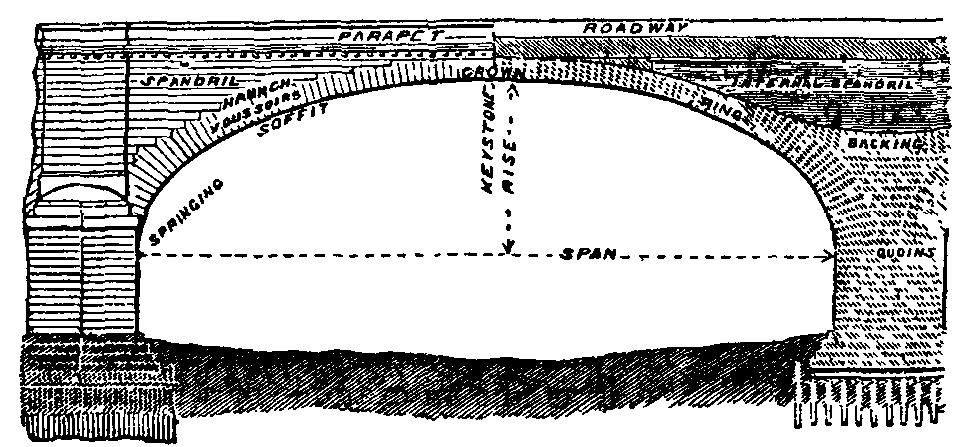
2. In a bridge there may be distinguished the superstructure and the substructure. In the former the main supporting member or members may be an arch ring or arched ribs, suspension chains or ropes, or a pair of girders, beams or trusses. The bridge flooring rests on the supporting members, and is of very various types according to the purpose of the bridge. There is also in large bridges wind-bracing to stiffen the structure against horizontal forces. The substructure consists of (a) the piers and end piers or abutments, the former sustaining a vertical load, and the latter having to resist, in addition, the oblique thrust of an arch, the pull of a suspension chain, or the thrust of an embankment; and (b) the foundations below the ground level, which are often difficult and costly parts of the structure, because the position of a bridge may be fixed by considerations which preclude the selection of a site naturally adapted for carrying a heavy structure.
3. Types of Bridges.—Bridges may be classed as arched bridges, in which the principal members are in compression; suspension bridges, in which the principal members are in tension; and girder bridges, in which half the components of the principal members are in compression and half in tension. But there are cases of bridges of mixed type. The choice of the type to be adopted depends on many and complex considerations:—(1) The cost, having regard to the materials available. For moderate spans brick, masonry or concrete can be used without excessive cost, but for longer spans steel is more economical, and for very long spans its use is imperative. (2) The importance of securing permanence and small cost of maintenance and repairs has to be considered. Masonry and concrete are more durable than metal, and metal than timber. (3) Aesthetic considerations sometimes have great weight, especially in towns. Masonry bridges are preferable in appearance to any others, and metal arch bridges are less objectionable than most forms of girder.
Most commonly the engineer has to attach great importance to the question of cost, and to design his structure to secure the greatest economy consistent with the provision of adequate strength. So long as bridge building was an empirical art, great waste of material was unavoidable. The development of the theory of structures has been largely directed to determining the arrangements of material which are most economical, especially in the superstructure. In the case of bridges of large span the cost and difficulty of erection are serious, and in such cases facility of erection becomes a governing consideration in the choice of the type to be adopted. In many cases the span is fixed by local conditions, such as the convenient sites for piers, or the requirements of waterway or navigation. But here also the question of economy must be taken into the reckoning. The cost of the superstructure increases very much as the span increases, but the greater the cost of the substructure, the larger the span which is economical. Broadly, the least costly arrangement is that in which the cost of the superstructure of a span is equal to that of a pier and foundation.
For masonry, brick or concrete the arch subjected throughout to compression is the most natural form. The arch ring can be treated as a blockwork structure composed of rigid voussoirs. The stability of such structures depends on the position of the line of pressure in relation to the extrados and intrados of the arch ring. Generally the line of pressure lies within the middle half of the depth of the arch ring. In finding the line of pressure some principle such as the principle of least action must be used in determining the reactions at the crown and springings, and some assumptions must be made of not certain validity. Hence to give a margin of safety to cover contingencies not calculable, an excess of material must be provided. By the introduction of hinges the position of the line of resistance can be fixed and the stress in the arch ring determined with less uncertainty. In some recent masonry arched bridges of spans up to 150 ft. built with hinges considerable economy has been obtained.
For an elastic arch of metal there is a more complete theory, but it is difficult of application, and there remains some uncertainty unless (as is now commonly done) hinges are introduced at the crown and springings.
In suspension bridges the principal members are in tension, and the introduction of iron link chains about the end of the 18th century, and later of wire ropes of still greater tenacity, permitted the construction of road bridges of this type with spans at that time impossible with any other system of construction. The suspension bridge dispenses with the compression member required in girders and with a good deal of the stiffening required in metal arches. On the other hand, suspension bridges require lofty towers and massive anchorages. The defect of the suspension bridge is its flexibility. It can be stiffened by girders and bracing and is then of mixed type, when it loses much of its advantage in economy. Nevertheless, the stiffened suspension bridge will probably be the type adopted in future for very great spans. A bridge on this system has been projected at New York of 3200 ft. span.
The immense extension of railways since 1830 has involved the construction of an enormous number of bridges, and most of these are girder bridges, in which about half the superstructure is in tension and half in compression. The use of wrought iron and later of mild steel has made the construction of such bridges very convenient and economical. So far as superstructure is concerned, more material must be used than for an arch or chain, for the girder is in a sense a combination of arch and chain. On the other hand, a girder imposes only a vertical load on its piers and abutments, and not a horizontal thrust, as in the case of an arch or suspension chain. It is also easier to erect.
A fundamental difference in girder bridges arises from the mode of support. In the simplest case the main girders are supported at the ends only, and if there are several spans they are discontinuous or independent. But a main girder may be supported at two or more points so as to be continuous over two [v.04 p.0534]or more spans. The continuity permits economy of weight. In a three-span bridge the theoretical advantage of continuity is about 49% for a dead load and 16% for a live load. The objection to continuity is that very small alterations of level of the supports due to settlement of the piers may very greatly alter the distribution of stress, and render the bridge unsafe. Hence many multiple-span bridges such as the Hawkesbury, Benares and Chittravatti bridges have been built with independent spans.
Lastly, some bridges are composed of cantilevers and suspended girders. The main girder is then virtually a continuous girder hinged at the points of contrary flexure, so that no ambiguity can arise as to the stresses.

Whatever type of bridge is adopted, the engineer has to ascertain the loads to be carried, and to proportion the parts so that the stresses due to the loads do not exceed limits found by experience to be safe. In many countries the limits of working stress in public and railway bridges are prescribed by law. The development of theory has advanced pari passu with the demand for bridges of greater strength and span and of more complex design, and there is now little uncertainty in calculating the stresses in any of the types of structure now adopted. In the modern metal bridge every member has a definite function and is subjected to a calculated straining action. Theory has been the guide in the development of bridge design, and its trustworthiness is completely recognized. The margin of uncertainty which must be met by empirical allowances on the side of safety has been steadily diminished.
The larger the bridge, the more important is economy of material, not only because the total expenditure is more serious, but because as the span increases the dead weight of the structure becomes a greater fraction of the whole load to be supported. In fact, as the span increases a point is reached at which the dead weight of the superstructure becomes so large that a limit is imposed to any further increase of span.

History of Bridge Building

4. Roman Bridges.—The first bridge known to have been constructed at Rome over the Tiber was the timber Pons Sublicius, the bridge defended by Horatius. The Pons Milvius, now Ponte Molle, was reconstructed in stone by M. Aemilius Scaurus in 109 B.C., and some portions of the old bridge are believed to exist in the present structure. The arches vary from 51 to 79 ft. span. The Pons Fabricius (mod. Ponte dei Quattro Capi), of about 62 B.C., is practically intact; and the Pons Cestius, built probably in 46 B.C., retains much of the original masonry. The Pons Aelius, built by Hadrian A.D. 134 and repaired by Pope Nicholas II. and Clement IX., is now the bridge of St Angelo. It had eight arches, the greatest span being 62 ft.#d1e4553/Footnote_061 Dio Cassius mentions a bridge, possibly 3000 to 4000 ft. in length, built by Trajan over the Danube in A.D. 104. Some piers are said still to exist. A bas-relief on the Trajan column shows this bridge with masonry piers and timber arches, but the representation is probably conventional (fig. 1). Trajan also constructed the bridge of Alcantara in Spain (fig. 2), of a total length of 670 ft., at 210 ft. above the stream. This had six arches and was built of stone blocks without cement. The bridge of Narses, built in the 6th century (fig. 3), carried the Via Salaria over the Anio. It was destroyed in 1867, during the approach of Garibaldi to Rome. It had a fortification such as became usual in later bridges for defence or for the enforcement of tolls. The great lines of aqueducts built by Roman engineers, and dating from 300 B.C. onwards, where they are carried above ground, are arched bridge structures of remarkable magnitude (see Aqueducts, § Roman). They are generally of brick and concrete.

5. Medieval and other Early Bridges.—Bridges with stone piers and timber superstructures were no doubt constructed from Roman times onward, but they have perished. Fig. 4 shows a timber bridge erected by the brothers Grubenmann at Schaffhausen about the middle of the 18th century. It had spans of 172 and 193 ft., and may be taken as a representative type of bridges of this kind. The Wittingen bridge by the same engineers had a span of 390 ft., probably the longest timber [v.04 p.0535]span ever constructed. Of stone bridges in Great Britain, the earliest were the cyclopean bridges still existing on Dartmoor, consisting of stone piers bridged by stone slabs. The bridge over the East Dart near Tavistock had three piers, with slabs 15 ft. by 6 ft. (Smiles, Lives of the Engineers, ii. 43). It is reputed to have lasted for 2000 years.

The curious bridge at Crowland near Peterborough (fig. 5) which now spans roadways, the streams which formerly flowed under it having been diverted, is one of the earliest known stone bridges in England. It is referred to in a charter of the year 943. It was probably built by the abbots. The first bridges over the Thames at London were no doubt of timber. William of Malmesbury mentions the existence of a bridge in 994. J. Stow (Survey of the Cities of London and Westminster) describes the building of the first stone bridge commonly called Old London Bridge: "About the year 1176, the stone bridge was begun to be founded by Peter of Colechurch, near unto the bridge of timber, but more towards the west." It carried timber houses (fig. 6) which were frequently burned down, yet the main structure existed till the beginning of the 19th century. The span of the arches ranged from 10 to 33 ft., and the total waterway was only 337 ft. The waterway of the present London Bridge is 690 ft., and the removal of the obstruction caused by the old bridge caused a lowering of the low-water level by 5 ft., and a considerable deepening of the river-bed. (See Smiles, Lives of the Engineers, "Rennie.")
From J. R Green's A Short History of the English People, by permission of Macmillan & Co., Ltd.

The architects of the Renaissance showed great boldness in their designs. A granite arch built in 1377 over the Adda at Trezzo had a span at low water of 251 ft. This noble bridge was destroyed for military reasons by Carmagnola in 1416. The Rialto bridge at Venice, with a span of 91 ft., was built in 1588 by Antonio da Ponte. Fig. 7 shows the beautiful Ponte dellà Trinità erected at Florence in 1566 from the design of B. Ammanati.
6. Modern Bridges.—(a) Timber.—In England timber bridges of considerable span, either braced trusses or laminated arches (i.e. arches of planks bolted together), were built for some of the earlier railways, particularly the Great Western and the Manchester, Sheffield & Lincolnshire. They have mostly been replaced, decay having taken place at the joints. Timber bridges of large span were constructed in America between the end of the 18th and the middle of the 19th century. The Amoskeag bridge over the Merrimac at Manchester, N.H., U.S.A., built in 1792, had 6 spans of 92 ft. The Bellows Falls bridge over the Connecticut (built 1785-1792) had 2 spans of 184 ft. The singular Colossus bridge, built in 1812 over the Schuylkill, a kind of flat arched truss, had a span of 340 ft. Some of these timber bridges are said to have lasted ninety years with ordinary repairs, but they were road bridges not heavily loaded. From 1840, trusses, chiefly of timber but with wrought-iron tension-rods and cast-iron shoes, were adopted in America. The Howe truss of 1830 and the Pratt truss of 1844 are examples. The Howe truss had timber chords and a lattice of timber struts, with vertical iron ties. In the Pratt truss the struts were vertical and the ties inclined. Down to 1850 such bridges were generally limited to 150 ft. span. The timber was white pine. As railway loads increased and greater spans were demanded, the Howe truss was stiffened by timber arches on each side of each girder. Such a composite structure is, however, fundamentally defective, the distribution of loading to the two independent systems being indeterminate. Remarkably high timber piers were built. The Genesee viaduct, 800 ft. in length, built in 1851-1852 in 10 spans, had timber trestle piers 190 ft. in height. (See Mosse, "American Timber Bridges," Proc. Inst. C.E. xxii. p. 305, and for more modern examples, cxlii. p. 409; and clv. p. 382; Cooper, "American Railroad Bridges," Trans. Am. Soc. C.E. vol. xxi pp. 1-28.) These timber framed structures served as models for the earlier metal trusses which began to be used soon after 1850, and which, except in a few localities where iron is costly, have quite superseded them.

7. (b) Masonry.—The present London Bridge, begun in 1824 and completed in 1831, is as fine an example of a masonry arch structure as can be found (figs. 8 and 9). The design was made by John Rennie the elder, and the acting engineer was his son, Sir John Rennie. The semi-elliptical shape of the arches the variation of span, the slight curvature of the roadway, and the simple yet bold architectural details, combine to make it a singularly beautiful bridge. The centre arch has a span of 152 ft., and rises 29 ft. 6 in above Trinity high-water mark; the arches on each side of the centre have a span of 140 ft. and the abutment arches 130 ft. The total length of the bridge is 1005 ft., its width from outside to outside 56 ft., and height above low [v.04 p.0536]water 60 ft. The two centre piers are 24 ft. thick, the exterior stones are granite, the interior, half Bramley Fall and half from Painshaw, Derbyshire. The voussoirs of the centre arch (all of granite) are 4 ft. 9 in. deep at the crown, and increase to not less than 9 ft. at the springing. The general depth at which the foundations are laid is about 29 ft. 6 in. below low water. The total cost was £1,458,311, but the contractor's tender for the bridge alone was £425,081.

Since 1867 it had been recognized that London Bridge was inadequate to carry the traffic passing over it, and a scheme for widening it was adopted in 1900. This was carried out in 1902-1904, the footways being carried on granite corbels, on which are mounted cornices and open parapets. The width between parapets is now 65 ft., giving a roadway of 35 ft. and two footways of 15 ft. each. The architect was Andrew Murray and the engineer, G. E. W. Cruttwell. (Cole, Proc. Inst. C.E. clxi. p. 290.)
The largest masonry arch is the Adolphe bridge in Luxemburg, erected in 1900-1903. This has a span of 278 ft., 138 ft. rise above the river, and 102 ft. from foundation to crown. The thickness of the arch is 4 ft. 8 in. at the crown and 7 ft. 2 in. where it joins the spandrel masonry. The roadway is 52 ft. 6 in. wide. The bridge is not continuous in width, there are arch rings on each face, each 16.4 ft. wide with a space between of 19.7 ft. This space is filled with a flooring of reinforced concrete, resting on the two arches, and carrying the central roadway. By the method adopted the total masonry has been reduced one-third. One centering was used for the two arch rings, supported on dwarf walls which formed a slipway, along which it was moved after the first was built.
Till near the end of the 19th century bridges of masonry or brickwork were so constructed that they had to be treated as rigid blockwork structures. The stability of such structures depends on the position of the line of pressure relatively to the intrados and extrados of the arch ring. Generally, so far as could be ascertained, the line of pressure lies within the middle half of the depth of the voussoirs. In finding the abutment reactions some principle such as the principle of least action must be used, and some assumptions of doubtful validity made. But if hinges are introduced at crown and springings, the calculation of the stresses in the arch ring becomes simple, as the line of pressures must pass through the hinges. Such hinges have been used not only for metal arches, but in a modified form for masonry and concrete arches. Three cases therefore arise: (a) The arch is rigid at crown and springings; (b) the arch is two-hinged (hinges at springings); (c) the arch is three-hinged (hinges at crown and springings). For an elementary account of the theory of arches, hinged or not, reference may be made to a paper by H. M. Martin (Proc. Inst. C. E. vol. xciii. p. 462); and for that of the elastic arch, to a paper by A.E.Young (Proc. Inst. C.E. vol. cxxxi. p. 323).
In Germany and America two- and three-hinged arches of masonry and concrete have been built, up to 150 ft. span, with much economy, and the calculations being simple, an engineer can venture to work closely to the dimensions required by theory. For hinges, Leibbrand, of Stuttgart, uses sheets of lead about 1 in. thick extending over the middle third of the depth of the voussoir joints, the rest of the joints being left open. As the lead is plastic this construction is virtually an articulation. If the pressure on the lead is uniformly varying, the centre of pressure must be within the middle third of the width of the lead; that is, it cannot deviate from the centre of the voussoir joint by more than one-eighteenth of its depth. In any case the position of the line of pressures is confined at the lead articulations within very narrow limits, and ambiguity as to the stresses is greatly diminished. The restricted area on which the pressure acts at the lead joints involves greater intensity of stress than has been usual in arched bridges. In the Württemberg hinged arches a limit of stress of 110 tons per sq. ft. was allowed, while in the unhinged arches at Cologne and Coblentz the limit was 50 to 60 tons per sq. ft. (Annales des Fonts et Chaussées, 1891). At Rechtenstein a bridge of two concrete arches has been constructed, span 75½ ft., with lead articulations: width of arch 11 ft.; depth of arch at crown and springing 2.1 and 2.96 ft. respectively. The stresses were calculated to be 15, 17 and 12 tons per sq. ft. at crown, joint of rupture, and springing respectively. At Cincinnati a concrete arch of 70 ft. span has been built, with a rise of 10 ft. The concrete is reinforced by eleven 9-in. steel-rolled joists, spaced 3 ft. apart and supported by a cross-channel joist at each springing. The arch is 15 in. thick at the crown and 4 ft. at the abutments. The concrete consisted of 1 cement, 2 sand and 3 to 4 broken stone. An important series of experiments on the strength of masonry, brick and concrete structures will be found in the Zeitschr. des österreichen Ing. und Arch. Vereines (1895).
The thermal coefficient of expansion of steel and concrete is nearly the same, otherwise changes of temperature would cause shearing stress at the junction of the two materials. If the two materials are disposed symmetrically, the amount of load carried by each would be in direct proportion to the coefficient of elasticity and inversely as the moment of inertia of the cross section. But it is usual in many cases to provide a sufficient section of steel to carry all the tension. For concrete the coefficient of elasticity E varies with the amount of stress and diminishes as the ratio of sand and stone to cement increases. Its value is generally taken at 1,500,000 to 3,000,000 lb per sq. in. For steel E = 28,000,000 to 30,000,000, or on the average about twelve times its value for concrete. The maximum compressive working stress on the concrete may be 500 lb per sq. in., the tensile working stress 50 lb per sq. in., and the working shearing stress 75 lb per sq. in. The tensile stress on the steel may be 16,000 lb per sq. in. The amount of steel in the structure may vary from 0.75 to 1.5%. The concrete not only affords much of the strength to resist compression, but effectively protects the steel from corrosion.
8. (c) Suspension Bridges.—A suspension bridge consists of two or more chains, constructed of links connected by pins, or of twisted wire strands, or of wires laid parallel. The chains pass over lofty piers on which they usually rest on saddles carried by rollers, and are led down on either side to anchorages in rock chambers. A level platform is hung from the chains by suspension rods. In the suspension bridge iron or steel can be used in its strongest form, namely hard-drawn wire. Iron suspension bridges began to be used at the end of the 18th century for road bridges with spans unattainable at that time in any other system. In 1819 T. Telford began the construction of the Menai bridge (fig. 10), the span being 570 ft. and the dip 43 ft. This bridge suffered some injury in a storm, but it is still in good condition and one of the most graceful of bridges. Other bridges built soon after were the Fribourg bridge of 870 ft. span, the Hammersmith bridge of 422 ft. span, and the Pest bridge of 666 ft. span. The merit of the simple suspension bridge is its cheapness, and its defect is its flexibility. This last becomes less [v.04 p.0537]serious as the dead weight of the structure becomes large in proportion to the live or temporary load. It is, therefore, a type specially suited for great spans. Some suspension bridges have broken down in consequence of the oscillations produced by bodies of men marching in step. In 1850 a suspension bridge at Angers gave way when 487 soldiers were marching over it, and 226 were killed.

To obtain greater stiffness various plans have been adopted. In the Ordish system a certain number of intermediate points in the span are supported by oblique chains, on which girders rest. The Ordish bridge built at Prague in 1868 had oblique chains supporting the stiffening girders at intermediate points of the span. A curved chain supported the oblique chains and kept them straight. In 1860 a bridge was erected over the Danube canal at Vienna, of 264 ft. span which had two parallel chains one above the other and 4 ft. apart on each side of the bridge. The chains of each pair were connected by bracing so that they formed a stiff inverted arch resisting deformation under unequal loading. The bridge carried a railway, but it proved weak owing to errors of calculation, and it was taken down in 1884. The principle was sound and has been proposed at various times. About 1850 it was perceived that a bridge stiff enough to carry railway trains could be constructed by combining supporting chains with stiffening girders suspended from them. W. J. M. Rankine proved (Applied Mechanics, p. 370) that the necessary strength of a stiffening girder would be only one-seventh part of that of an independent girder of the same span as the bridge, suited to carry the same moving load (not including the dead weight of the girder which is supported by the chain). (See "Suspension Bridge with Stiffened Roadway," by Sir G. Airy, and the discussion, Proc. Inst, C.E., 1867, xxvi. p. 258; also "Suspension Bridges with Stiffening Girders," by Max am Ende, Proc. Inst. C.E. cxxxvii. p. 306.)

The most remarkable bridge constructed on this system was the Niagara bridge built by J. A. Roebling in 1852-1855 (fig. 11). The span was 821 ft., much the largest of any railway bridge at that time, and the height above the river 245 ft. There were four suspension cables, each 10 in. in diameter; each was composed of seven strands, containing 520 parallel wires, or 3640 wires in each cable. Each cable was carried on a separate saddle on rollers on each pier. The stiffening girder, constructed chiefly of timber, was a box-shaped braced girder 18 ft. deep and 25 ft. wide, carrying the railway on top and a roadway within. After various repairs and strengthenings, including the replacement of the timber girder by an iron one in 1880, this bridge in 1896-1897 was taken down and a steel arch built in its place. It was not strong enough to deal with the increasing weight of railway traffic. In 1836 I. K. Brunei constructed the towers and abutments for a suspension bridge of 702 ft. span at Clifton over the Avon, but the project was not then carried further; in 1860, however, the link chains of the Hungerford suspension bridge which was being taken down were available at small cost, and these were used to complete the bridge. There are three chains on each side, of one and two links alternately, and these support wrought iron stiffening girders. There are wrought iron saddles and steel rollers on the piers. At 196 ft. on either side from the towers the chains are carried over similar saddles without rollers, and thence at 45° with the horizontal down to the anchorages. Each chain has an anchor plate 5 ft. by 6 ft. The links are 24 ft. long at the centre of the bridge, and longer as they are more inclined, so that their horizontal projection is 24 ft. The chains are so arranged that there is a suspending rod at each 8 ft., attached at the joint of one of the three chains. For erection a suspended platform was constructed on eight wire ropes, on which the chains were laid out and connected. Another wire rope with a travelling carriage took out the links. The sectional area of the chains is 481 sq. in. at the piers and 440 sq. in. at the centre. The two stiffening girders are plate girders 3 ft. deep with flanges of 11 sq. in. area. In addition, the hand railing on each side forms a girder 4 ft. 9 in. deep, with flanges 4½ sq. in. area.

Of later bridges of great span, perhaps the bridges over the East river at New York are the most remarkable. The Brooklyn bridge, begun in 1872, has a centre span of 1595½ and side spans of 930 ft. The Brooklyn approach being 971 ft., and the New York approach 1562½ ft., the total length of the bridge is 5989 ft. There are four cables which carry a promenade, a roadway and an electric railway. The stiffening girders of the main span are 40 ft. deep and 67 ft. apart. The saddles for the chains are 329 ft. above high water. The cables are 15¾ in. in diameter. Each cable has 19 strands of 278 parallel steel wires, 7 B.W.G. Each wire is taken separately across the river and its length adjusted. Roebling preferred parallel wires as 10 % stronger than twisted wires. Each strand when made up and clamped was lowered to its position. The Williamsburg bridge (fig. 12), begun in 1897 and opened for traffic in 1903, has a span of 1600 ft., a versed sine of 176 ft., and a width of 118 ft. It has two decks, and carries two elevated railway tracks, four electric tramcar lines, two carriageways, two footways and two [v.04 p.0538]bicycle paths. There are four cables, one on each side of the two main trusses or stiffening girders. These girders are supported by the cables over the centre span but not in the side spans. Intermediate piers support the trusses in the side spans. The cables are 18¾ in. in diameter; each weighs about 1116 tons, and has a nominal breaking strength of 22,320 tons, the actual breaking strength being probably greater. The saddles are 332 ft. above the water. The four cables support a dead load of 7140 tons and a live load of 4017 tons. Each cable is composed of 37 strands of 208 wires, or 7696 parallel steel wires, No. 8 B.W.G., or about 3/16 in. in diameter. The wire was required to have a tensile strength of 89 tons per sq. in., and 2½% elongation in 5 ft. and 5% in 8 in. Cast steel clamps hold the cable together, and to these the suspending rods are attached. The cables are wrapped in cotton duck soaked in oxidized oil and varnish, and are sheathed in sheet iron. A later bridge, the Manhattan, is designed to carry four railway tracks and four tramway lines, with a wide roadway and footpaths, supported by cables 21¼ in. in diameter, each composed of 9472 galvanized steel wires 3/16 in. in diameter.

The Tower Bridge, London (fig. 13), is a suspension bridge with a secondary bascule bridge in the centre span to permit the passage of ships. Two main towers in the river and two towers on the shore abutments carry the suspension chains. The opening bridge between the river towers consists of two leaves or bascules, pivoted near the faces of the piers and rotating in a vertical plane. When raised, the width of 200 ft. between the main river piers is unobstructed up to the high-level foot-bridge, which is 141 ft. above Trinity H.W. The clear width of the two shore spans is 270 ft. The total length of the bridge is 940 ft., and that of the approaches 1260 ft. on the north and 780 ft. on the south. The width of the bridge between parapets is 60 ft., except across the centre span, where it is 49 ft. The main towers consist of a skeleton of steel, enclosed in a facing of granite and Portland stone, backed with brickwork. There are two high-level footways for use when the bascules are raised, the main girders of which are of the cantilever and suspended girder type. The cantilevers are fixed to the shore side of the towers. The middle girders are 120 ft. in length and attached to the cantilevers by links. The main suspension chains are carried across the centre span in the form of horizontal ties resting on the high-level footway girders. These ties are jointed to the hanging chains by pins 20 in. in diameter with a ring in halves surrounding it 5 in. thick. One half ring is rigidly attached to the tie and one to the hanging chain, so that the wear due to any movement is distributed over the length of the pin. A rocker bearing under these pins transmits the load at the joint to the steel columns of the towers. The abutment towers are similar to the river towers. On the abutment towers the chains are connected by horizontal links, carried on rockers, to anchor ties. The suspension chains are constructed in the form of braced girders, so that they are stiff against unsymmetrical loading. Each chain over a shore span consists of two segments, the longer attached to the tie at the top of the river tower, the shorter to the link at the top of the abutment tower, and the two jointed together at the lowest point. Transverse girders are hung from the chains at distances of 18 ft. There are fifteen main transverse girders to each shore span, with nine longitudinal girders between each pair. The trough flooring, ⅜ in. thick and 6 in. deep, is riveted to the longitudinals. The anchor ties are connected to girders embedded in large concrete blocks in the foundations of the approach viaducts.
The two bascules are each constructed with four main girders. Over the river these are lattice girders, with transverse girders 12 ft. apart, and longitudinal and subsidiary transverse girders dividing the floor into rectangles 3 ft. by 3½ ft. covered with buckled plates. The roadway is of pine blocks dowelled. The bascules rotate through an angle of 82°, and their rear ends in the bascule chambers of the piers carry 365 tons of counterweight, the total weight of each being 1070 tons. They rotate on steel shafts 21 in. in diameter and 48 ft. long, and the bascules can be lifted or lowered in one minute, but usually the time taken is one and a half minutes. They are worked by hydraulic machinery.
9. (d) Iron and Steel Girder Bridges.—The main supporting members are two or more horizontal beams, girders or trusses. The girders carry a floor or platform either on top (deck bridges) or near the bottom (through bridges). The platform is variously constructed. For railway bridges it commonly consists of cross girders, attached to or resting on the main girders, and longitudinal rail girders or stringers carried by the cross girders and directly supporting the sleepers and rails. For spans over 75 ft., expansion due to change of temperature is provided for by carrying one end of each chain girder on rollers placed between the bearing-plate on the girder and the bed-plate on the pier or abutment.
Fig. 14 shows the roller bed of a girder of the Kuilenburg bridge of 490 ft. span. It will be seen that the girder directly rests on a cylindrical pin or rocker so placed as to distribute the load uniformly to all the rollers. The pressure on the rollers is limited to about p = 600 d in lb per in. length of roller, where d is the diameter of the roller in inches.

In the girders of bridges the horizontal girder is almost exclusively subjected to vertical loading forces. Investigation of the internal stresses, which balance the external forces, shows that most of the material should be arranged in a top flange, boom or chord, subjected to compression, and a bottom flange or chord, subjected to tension. (See Strength of Materials.) Connecting the flanges is a vertical web which may be a solid plate or a system of bracing bars. In any case, though the exact form of cross section of girders varies very much, it is virtually an I section (fig. 15). The function of the flanges is to resist a horizontal tension and compression distributed practically uniformly on their cross sections. The web resists forces equivalent [v.04 p.0539]to a shear on vertical and horizontal planes. The inclined tensions and compressions in the bars of a braced web are equivalent to this shear. The horizontal stresses in the flanges are greatest at the centre of a span. The stresses in the web are greatest at the ends of the span. In the most numerous cases the flanges or chords are parallel. But girders may have curved chords and then the stresses in the web are diminished.

At first girders had solid or plate webs, but for spans over 100 ft. the web always now consists of bracing bars. In some girder bridges the members are connected entirely by riveting, in others the principal members are connected by pin joints. The pin system of connexion used in the Chepstow, Saltash, Newark Dyke and other early English bridges is now rarely used in Europe. But it is so commonly used in America as to be regarded as a distinctive American feature. With pin connexions some weight is saved in the girders, and erection is a little easier. In early pin bridges insufficient bearing area was allowed between the pins and parts connected, and they worked loose. In some cases riveted covers had to be substituted for the pins. The proportions are now better understood. Nevertheless the tendency is to use riveted connexions in preference to pins, and in any case to use pins for tension members only.
On the first English railways cast iron girder bridges for spans of 20 to 66 ft. were used, and in some cases these were trussed with wrought iron. When in 1845 the plans for carrying the Chester and Holyhead railway over the Menai Straits were considered, the conditions imposed by the admiralty in the interests of navigation involved the adoption of a new type of bridge. There was an idea of using suspension chains combined with a girder, and in fact the tower piers were built so as to accommodate chains. But the theory of such a combined structure could not be formulated at that time, and it was proved, partly by experiment, that a simple tubular girder of wrought iron was strong enough to carry the railway. The Britannia bridge (fig. 16) has two spans of 460 and two of 230 ft. at 104 ft. above high water. It consists of a pair of tubular girders with solid or plate sides stiffened by angle irons, one line of rails passing through each tube. Each girder is 1511 ft. long and weighs 4680 tons. In cross section (fig. 17), it is 15 ft. wide and varies in depth from 23 ft. at the ends to 30 ft. at the centre. Partly to counteract any tendency to buckling under compression and partly for convenience in assembling a great mass of plates, the top and bottom were made cellular, the cells being just large enough to permit passage for painting. The total area of the cellular top flange of the large-span girders is 648 sq. in., and of the bottom 585 sq. in. As no scaffolding could be used for the centre spans, the girders were built on shore, floated out and raised by hydraulic presses. The credit for the success of the Conway and Britannia bridges must be divided between the engineers. Robert Stephenson and William Fairbairn, and Eaton Hodgkinson, who assisted in the experimental tests and in formulating the imperfect theory then available. The Conway bridge was first completed, and the first train passed through the Britannia bridge in 1850. Though each girder has been made continuous over the four spans it has not quite the proportions over the piers which a continuous girder should have, and must be regarded as an imperfectly continuous girder. The spans were in fact designed as independent girders, the advantage of continuity being at that time imperfectly known. The vertical sides of the girders are stiffened so that they amount to 40% of the whole weight. This was partly necessary to meet the uncertain conditions in floating when the distribution of supporting forces was unknown and there were chances of distortion.


Wrought iron and, later, steel plate web girders were largely used for railway bridges in England after the construction of the Conway and Menai bridges, and it was in the discussions arising during their design that the proper function of the vertical web between the top and bottom flanges of a girder first came to be understood. The proportion of depth to span in the Britannia bridge was 1/16. But so far as the flanges are concerned the stress [v.04 p.0540]to be resisted varies inversely as the depth of the girder. It would be economical, therefore, to make the girder very deep. This, however, involves a much heavier web, and therefore for any type of girder there must be a ratio of depth to span which is most economical. In the case of the plate web there must be a considerable excess of material, partly to stiffen it against buckling and partly because an excess of thickness must be provided to reduce the effect of corrosion. It was soon found that with plate webs the ratio of depth to span could not be economically increased beyond 1/15 to 1/12. On the other hand a framed or braced web afforded opportunity for much better arrangement of material, and it very soon became apparent that open web or lattice or braced girders were more economical of material than solid web girders, except for small spans. In America such girders were used from the first and naturally followed the general design of the earlier timber bridges. Now plate web girders are only used for spans of less than 100 ft.
Three types of bracing for the web very early developed—the Warren type in which the bracing bars form equilateral triangles, the Whipple Murphy in which the struts are vertical and the ties inclined, and the lattice in which both struts and ties are inclined at equal angles, usually 45° with the horizontal. The earliest published theoretical investigations of the stresses in bracing bars were perhaps those in the paper by W.T. Doyne and W.B. Blood (Proc. Inst. C.E., 1851, xi. p. 1), and the paper by J. Barton, "On the economic distribution of material in the sides of wrought iron beams" (Proc. Inst. C.E., 1855, xiv. p. 443).

The Boyne bridge, constructed by Barton in Ireland, in 1854-1855, was a remarkable example of the confidence with which engineers began to apply theory in design. It was a bridge for two lines of railway with lattice girders continuous over three spans. The centre span was 264 ft., and the side spans 138 ft. 8 in.; depth 22 ft. 6 in. Not only were the bracing bars designed to calculated stresses, and the continuity of the girders taken into account, but the validity of the calculations was tested by a verification on the actual bridge of the position of the points of contrary flexure of the centre span. At the calculated position of one of the points of contrary flexure all the rivets of the top boom were cut out, and by lowering the end of the girder over the side span one inch, the joint was opened 1/32 in. Then the rivets were cut out similarly at the other point of contrary flexure and the joint opened. The girder held its position with both joints severed, proving that, as should be the case, there was no stress in the boom where the bending moment changes sign.

By curving the top boom of a girder to form an arch and the bottom boom to form a suspension chain, the need of web except for non-uniform loading is obviated. I.K. Brunel adopted this principle for the Saltash bridge near Plymouth, built soon after the Britannia bridge. It has two spans of 455 ft. and seventeen smaller spans, the roadway being 100 ft. above high water. The top boom of each girder is an elliptical wrought iron tube 17 ft. wide by 12 ft. deep. The lower boom is a pair of chains, of wrought-iron links, 14 in each chain, of 7 in. by 1 in. section, the links being connected by pins. The suspending rods and cross bracing are very light. The depth of the girder at the centre is about one-eighth of the span.

In both England and America in early braced bridges cast iron, generally in the form of tubes circular or octagonal in section, was used for compression members, and wrought iron for the tension members. Fig. 19 shows the Newark Dyke bridge on the Great Northern railway over the Trent. It was a pin-jointed Warren girder bridge erected from designs by C.M. Wild in 1851-1853. The span between supports was 259 ft., the clear span 240½ ft.; depth between joint pins 16 ft. There were four girders, two to each line of way. The top flange consisted of cast iron hollow castings butted end to end, and the struts were of cast iron. The lower flange and ties were flat wrought iron links. This bridge has now been replaced by a stronger bridge to carry the greater loads imposed by modern traffic. Fig. 20 shows a Fink truss, a characteristic early American type, with cast iron compression and wrought iron tension members. The bridge is a deck bridge, the railway being carried on top. The transfer of the loads to the ends of the bridge by [v.04 p.0541]long ties is uneconomical, and this type has disappeared. The Warren type, either with two sets of bracing bars or with intermediate verticals, affords convenient means of supporting the floor girders. In 1869 a bridge of 390 ft. span was built on this system at Louisville.
Amongst remarkable American girder bridges may be mentioned the Ohio bridge on the Cincinnati & Covington railway, which is probably the largest girder span constructed. The centre span is 550 ft. and the side spans 490 ft.—centre to centre of piers. The girders are independent polygonal girders. The centre girder has a length of 545 ft. and a depth of 84 ft. between pin centres. It is 67 ft. between parapets, and carries two lines of railway, two carriageways, and two footways. The cross girders, stringers and wind-bracing are wrought iron, the rest of mild steel. The bridge was constructed in 1888 by the Phoenix Bridge Company, and was erected on staging. The total weight of iron and steel in three spans was about 5000 tons.


10. (e) Cantilever Bridges.—It has been stated that if in a girder bridge of three or more spans, the girders were made continuous there would be an important economy of material, but that the danger of settlement of the supports, which would seriously alter the points of contrary flexure or points where the bending moment changes sign, and therefore the magnitude and distribution of the stresses, generally prevents the adoption of continuity. If, however, hinges or joints are introduced at the points of contrary flexure, they become necessarily points where the bending moment is zero and ambiguity as to the stresses vanishes. The exceptional local conditions at the site of the Forth bridge led to the adoption there of the cantilever system, till then little considered. Now it is well understood that in many positions this system is the simplest and most economical method of bridging. It is available for spans greater than those practicable with independent girders; in fact, on this system the spans are virtually reduced to smaller spans so far as the stresses are concerned. There is another advantage which in many cases is of the highest importance. The cantilevers can be built out from the piers, member by member, without any temporary scaffolding below, so that navigation is not interrupted, the cost of scaffolding is saved, and the difficulty of building in deep water is obviated. The centre girder may be built on the cantilevers and rolled into place or lifted from the water-level. Fig. 21 shows a typical cantilever bridge of American design. In this case the shore ends of the cantilevers are anchored to the abutments. J.A.L. Waddell has shown that, in some cases, it is convenient to erect simple independent spans, by building them out as cantilevers and converting them into independent girders after erection. Fig. 22 shows girders erected in this way, the dotted lines being temporary members during erection, which are removed afterwards. The side spans are erected first on staging and anchored to the piers. From these, by the aid of the temporary members, the centre span is built out from both sides. The most important cantilever bridges so far erected or projected are as follows:—

(1) The Forth bridge (fig. 23). The original design was for a stiffened suspension bridge, but after the fall of the Tay bridge in 1879 this was abandoned. The bridge, which was begun in 1882 and completed in 1889, is at the only narrowing of the Forth in a distance of 50 m., at a point where the channel, about a mile in width, is divided by the island of Inchgarvie. The length of the cantilever bridge is 5330 ft., made up thus: central tower on Inchgarvie 260 ft.; Fife and Queensferry piers each 145 ft.; two central girders between cantilevers each 350 ft.; and six cantilevers each 680 ft. The two main spans are each 1710 ft. The clear headway is 157 ft., and the extreme height of the towers above high water 361 ft. The outer ends of the shore cantilevers are loaded to balance half the weight of the central girder, the rolling load, and 200 tons in addition. An internal viaduct of lattice girders carries a double line of rails. Provision is made for longitudinal expansion due to change of temperature, for distortion due to the sun acting on one side of the structure, and for the wind acting on one side of the bridge. The amount of steel used was 38,000 tons exclusive of approach viaducts. (See The Forth Bridge, by W. Westhofen; Reports of the British Association (1884 and 1885); Die Forth Brücke, von G. Barkhausen (Berlin, 1889); The Forth Bridge, by Philip Phillips (1890); Vernon Harcourt, Proc. Inst. C.E. cxxi. p. 309.)
(2) The Niagara bridge of a total length of 910 ft., for two lines of railway. Clear span between towers 495 ft. Completed in 1883, and more recently strengthened (Proc. Inst. C.E. cvii. p. 18, and cxliv. p. 331).

(3) The Lansdowne bridge (completed 1889) at Sukkur, over the Indus. The clear span is 790 ft., and the suspended girder 200 ft. in length. The span to the centres of the end uprights is 820 ft.; width between centres of main uprights at bed-plate 100 ft., and between centres of main members at end of cantilevers 20 ft. The bridge is for a single line of railway of 5 ft. 6 in. gauge. The back guys are the most heavily strained part of the structure, the stress provided for being 1200 tons. This is due to the half weight of centre girder, the weight of the cantilever itself, the rolling load on half the bridge, and the wind pressure. The anchors are built up of steel plates and angle, bars, and are buried in a large mass of concrete. The area of each anchor plate, normal to the line of stress, is 32 ft. by 12 ft. The bridge was designed by Sir A. Rendel, the consulting engineer to the Indian government (Proc. Inst. C.E. ciii. p. 123).
(4) The Red Rock cantilever bridge over the Colorado river, with a centre span of 660 ft.
(5) The Poughkeepsie bridge over the Hudson, built 1886-1887. There are five river and two shore spans. The girders over the second and fourth spans are extended as cantilevers over the adjoining spans. The shore piers carry cantilevers projecting one way over the river openings and the other way over a shore span where it is secured to an anchorage. The girder spans are 525 ft., the cantilever spans 547 ft., and the shore spans 201 ft.
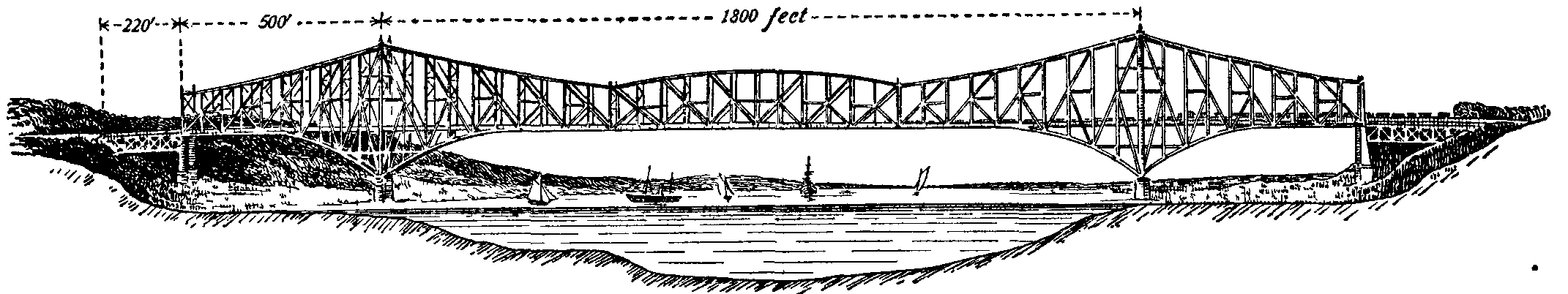
(6) The Quebec bridge (fig. 25) over the St Lawrence, which collapsed while in course of construction in 1907. This bridge, connecting very important railway systems, was designed to carry two lines of rails, a highway and electric railway on each side, all between the main trusses. Length between abutments 3240 ft.; [v.04 p.0542]channel span 1800 ft.; suspended span 675 ft.; shore spans 562½ ft. Total weight of metal about 32,000 tons.

(7) The Jubilee bridge over the Hugli, designed by Sir Bradford Leslie, is a cantilever bridge of another type (fig. 26). The girders are of the Whipple Murphy type, but with curved top booms. The bridge carries a double line of railway, between the main girders. The central double cantilever is 360 ft. long. The two side span girders are 420 ft long. The cantilever rests on two river piers 120 ft. apart, centre to centre. The side girders rest on the cantilevers on 15 in. pins, in pendulum links suspended from similar pins in saddles 9 ft. high.

11. (f) Metal Arch Bridges.—The first iron bridge erected was constructed by John Wilkinson (1728-1808) and Abraham Darby (1750-1791) in 1773-1779 at Coalbrookdale over the Severn (fig. 27). It had five cast iron arched ribs with a centre span of 100 ft. This curious bridge is still in use. Sir B. Baker stated that it had required patching for ninety years, because the arch and the high side arches would not work together. Expansion and contraction broke the high arch and the connexions between the arches. When it broke they fished it. Then the bolts sheared or the ironwork broke in a new place. He advised that there was nothing unsafe; it was perfectly strong and the stress in vital parts moderate. All that needed to be done was to fish the fractured ribs of the high arches, put oval holes in the fishes, and not screw up the bolts too tight.
Cast iron arches of considerable span were constructed late in the 18th and early in the 19th century. The difficulty of casting heavy arch ribs led to the construction of cast iron arches of cast voussoirs, somewhat like the voussoirs of masonry bridges. Such a bridge was the Wearmouth bridge, designed by Rowland Burdon and erected in 1793-1796, with a span of 235 ft. Southwark bridge over the Thames, designed by John Rennie with cast iron ribs and erected in 1814-1819, has a centre span of 240 ft. and a rise of 24 ft. In Paris the Austerlitz (1800-1806) and Carrousel (1834-1836) bridges had cast iron arches. In 1858 an aqueduct bridge was erected at Washington by M.C. Meigs (1816-1892). This had two arched ribs formed by the cast iron pipes through which the water passed. The pipes were 4 ft. in diameter inside, 1½ in. thick, and were lined with staves of pine 3 in. thick to prevent freezing. The span was 200 ft.
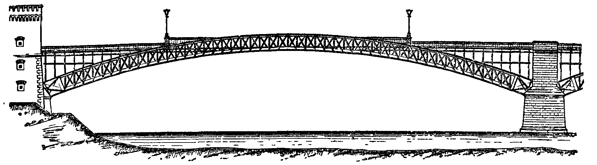
Fig. 28 shows one of the wrought iron arches of a bridge over the Rhine at Coblenz. The bridge consists of three spans of about 315 ft. each.

Of large-span bridges with steel arches, one of the most important is the St Louis bridge over the Mississippi, completed in 1874 (fig. 29). The river at St Louis is confined to a single channel, 1600 ft. wide, and in a freshet in 1870 the scour reached a depth of 51 ft. Captain J.B. Eads, the engineer, determined to establish the piers and abutments on rock at a depth for the east pier and east abutment of 136 ft. below high water. This was effected by caissons with air chambers and air locks, a feat unprecedented in the annals of engineering. The bridge has three spans, each formed of arches of cast steel. The centre span is 520 ft. and the side spans 502 ft. in the clear. The rise of the centre arch is 47½ ft., and that of the side arches 46 ft. Each span has four steel double ribs of steel tubes butted and clasped by wrought iron couplings. The vertical bracing between the upper and lower members of each rib, which are 12 ft. apart, centre to centre, consolidates them into a single arch. The arches carry a double railway track and above this a roadway 54 ft. wide.
The St Louis bridge is not hinged, but later bridges have been constructed with hinges at the springings and sometimes with hinges at the crown also.
The Alexander III. bridge over the Seine has fifteen steel ribs hinged at crown and springings with a span of 353 ft. between centres of hinges and 358 ft. between abutments. The rise from side to centre hinges is 20 ft. 7 in. The roadway is 65½ ft. wide and footways 33 ft. (Proc. Inst. C.E. cxxx. p. 335).

The largest three-hinged-arch bridge constructed is the Viaur viaduct in the south of France (fig. 30). The central span is 721 ft. 9 in. and the height of the rails above the valley 380 ft. It has a very fine appearance, especially when seen in perspective and not merely in elevation.

Fig. 31 shows the Douro viaduct of a total length of 1158 ft. carrying a railway 200 ft. above the water. The span of the central opening is 525 ft. The principal rib is crescent-shaped 32.8 ft. deep [v.04 p.0543]at the crown. Rolling load taken at 1.2 ton per ft. Weight of centre span 727 tons. The Luiz I. bridge is another arched bridge over the Douro, also designed by T. Seyrig. This has a span of 566 ft. There are an upper and lower roadway, 164 ft. apart vertically. The arch rests on rollers and is narrowest at the crown. The reason given for this change of form was that it more conveniently allowed the lower road to pass between the springings and ensured the transmission of the wind stresses to the abutments without interrupting the cross-bracing. Wire cables were used in the erection, by which the members were lifted from barges and assembled, the operations being conducted from the side piers.

The Niagara Falls and Clifton steel arch (fig. 32) replaces the older Roebling suspension bridge. The centre span is a two-hinged parabolic braced rib arch, and there are side spans of 190 and 210 ft. The bridge carries two electric-car tracks, two roadways and two footways. The main span weighed 1629 tons, the side spans 154 and 166 tons (Buck, Proc. Inst. C.E. cxliv. p. 70). Prof. Claxton Fidler, speaking of the arrangement adopted for putting initial stress on the top chord, stated that this bridge marked the furthest advance yet made in this type of construction. When such a rib is erected on centering without initial stress, the subsequent compression of the arch under its weight inflicts a bending stress and excess of compression in the upper member at the crown. But the bold expedients adopted by the engineer annulled the bending action.
The Garabit viaduct carries the railway near St Flour, in the Cantal department, France, at 420 ft. above low water. The deepest part of the valley is crossed by an arch of 541 ft. span, and 213 ft. rise. The bridge is similar to that at Oporto, also designed by Seyrig. It is formed by a crescent-shaped arch, continued on one side by four, on the other side by two lattice girder spans, on iron piers. The arch is formed by two lattice ribs hinged at the abutments. Its depth at the crown is 33 ft., and its centre line follows nearly the parabolic line of pressures. The two arch ribs are 65½ ft. apart at the springings and 20½ ft. at the crown. The roadway girders are lattice, 17 ft. deep, supported from the arch ribs at four points. The total length of the viaduct is 1715 ft. The lattice girders of the side spans were first rolled into place, so as to project some distance beyond the piers, and then the arch ribs were built out, being partly supported by wire-rope cables from the lattice girders above. The total weight of ironwork was 3200 tons and the cost £124,000 (Annales des travaux publiques, 1884).
The Victoria Falls bridge over the Zambezi, designed by Sir Douglas Fox, and completed in 1905, is a combination of girder and arch having a total length of 650 ft. The centre arch is 500 ft. span, the rise of the crown 90 ft., and depth at crown 15 ft. The width between centres of ribs of main arch is 27½ ft. at crown and 53 ft. 9 in at springings. The curve of the main arch is a parabola. The bridge has a roadway of 30 ft. for two lines of rails. Each half arch was supported by cables till joined at the centre. An electric cableway of 900 ft. span capable of carrying 10 tons was used in erection.
12. (g) Movable Bridges can be closed to carry a road or railway or in some cases an aqueduct, but can be opened to give free passage to navigation. They are of several types:—

(1) Lifting Bridges.—The bridge with its platform is suspended from girders above by chains and counterweights at the four corners (fig. 33 a). It is lifted vertically to the required height when opened. Bridges of this type are not very numerous or important.
(2) Rolling Bridges.—The girders are longer than the span and the part overhanging the abutment is counter-weighted so that the centre of gravity is over the abutment when the bridge is rolled forward (fig. 33 b). To fill the gap in the approaches when the bridge is rolled forward a frame carrying that part of the road is moved into place sideways. At Sunderland, the bridge is first lifted by a hydraulic press so as to clear the roadway behind, and is then rolled back.
(3) Draw or Bascule Bridges.—The fortress draw-bridge is the original type, in which a single leaf, or bascule, turns round a horizontal hinge at one abutment. The bridge when closed is supported on abutments at each end. It is raised by chains and counterweights. A more common type is a bridge with two leaves or bascules, one hinged at each abutment. When closed [v.04 p.0544]the bascules are locked at the centre (see fig. 13). In these bridges each bascule is prolonged backwards beyond the hinge so as to balance at the hinge, the prolongation sinking into the piers when the bridge is opened.
(4) Swing or Turning Bridges.—The largest movable bridges revolve about a vertical axis. The bridge is carried on a circular base plate with a central pivot and a circular track for a live ring and conical rollers. A circular revolving platform rests on the pivot and rollers. A toothed arc fixed to the revolving platform or to the live ring serves to give motion to the bridge. The main girders rest on the revolving platform, and the ends of the bridge are circular arcs fitting the fixed roadway. Three arrangements are found: (a) the axis of rotation is on a pier at the centre of the river and the bridge is equal armed (fig. 33 c), so that two navigation passages are opened simultaneously. (b) The axis of rotation is on one abutment, and the bridge is then usually unequal armed (fig. 33 d), the shorter arm being over the land. (c) In some small bridges the shorter arm is vertical and the bridge turns on a kind of vertical crane post at the abutment (fig. 33 e).
(5) Floating Bridges, the roadway being carried on pontoons moored in the stream.
The movable bridge in its closed position must be proportioned like a fixed bridge, but it has also other conditions to fulfil. If it revolves about a vertical axis its centre of gravity must always lie in that axis; if it rolls the centre of gravity must always lie over the abutment. It must have strength to support safely its own overhanging weight when moving.
At Konigsberg there is a road bridge of two fixed spans of 39 ft., and a central span of 60 ft. between bearings, or 41 ft. clear, with balanced bascules over the centre span. Each bascule consists of two main girders with cross girders and stringers. The main girders are hung at each side on a horizontal shaft 8⅝ in. in diameter, and are 6 ft. deep at the hinge, diminishing to 1 ft. 7 in. at the centre of the span. The counterweight is a depressed cantilever arm 12 ft. long, overlapped by the fixed platform which sinks into a recess in the masonry when the bridge opens. In closed position the main girders rest on a bed plate on the face of the pier 4 ft. 3 in. beyond the shaft bearings. The bridge is worked by hydraulic power, an accumulator with a load of 34 tons supplying pressure water at 630 lb per sq. in. The bridge opens in 15 seconds and closes in 25 seconds.
At the opening span of the Tower bridge (fig. 13) there are four main girders in each bascule. They project 100 ft. beyond and 62 ft. 6 in. within the face of the piers. Transverse girders and bracings are inserted between the main girders at 12 ft. intervals. The floor is of buckled plates paved with wood blocks. The arc of rotation is 82°, and the axis of rotation is 13 ft. 3 in. inside the face of the piers, and 5 ft. 7 in. below the roadway. The weight of ballast in the short arms of the bascules is 365 tons. The weight of each leaf including ballast is about 1070 tons. The axis is of forged steel 21 in. in diameter and 48 ft. long. The axis has eight bearings, consisting of rings of live rollers 4-7/16 in. in diameter and 22 in. long. The bascules are rotated by pinions driven by hydraulic engines working in steel sectors 42 ft. radius (Proc. Inst. C.E. cxxvii. p. 35).
As an example of a swing bridge, that between Duluth and Superior at the head of Lake Superior over the St Louis river may be described. The centre opening is 500 ft., spanned by a turning bridge, 58 ft. wide. The girders weighing 2000 tons carry a double track for trains between the girders and on each side on cantilevers a trolley track, roadway and footway. The bridge can be opened in 2 minutes, and is operated by two large electric motors. These have a speed reduction from armature shaft to bridge column of 1500 to 1, through four intermediate spur gears and a worm gear. The end lifts which transfer the weight of the bridge to the piers when the span is closed consist of massive eccentrics having a throw of 4 in. The clearance is 2 in., so that the ends are lifted 2 in. This gives a load of 50 tons per eccentric. One motor is placed at each end of the span to operate the eccentrics and also to release the latches and raise the rails of the steam track.
At Riga there is a floating pontoon bridge over the Duna. It consists of fourteen rafts, 105 ft. in length, each supported by two pontoons placed 64 ft. apart. The pairs of rafts are joined by three baulks 15 ft. long laid in parallel grooves in the framing. Two spans are arranged for opening easily. The total length is 1720 ft. and the width 46 ft. The pontoons are of iron, 85½ ft. in length, and their section is elliptical, 10½ ft. horizontal and 12 ft. vertical. The displacement of each pontoon is 180 tons and its weight 22 tons. The mooring chains, weighing 22 lb per ft., are taken from the upstream end of each pontoon to a downstream screw pile mooring and from the downstream end to an upstream screw pile.
13. Transporter Bridges.—This new type of bridge consists of a high level bridge from which is suspended a car at a low level. The car receives the traffic and conveys it across the river, being caused to travel by electric machinery on the high level bridge. Bridges of this type have been erected at Portugalete, Bizerta, Rouen, Rochefort and more recently across the Mersey between the towns of Widnes and Runcorn.

The Runcorn bridge crosses the Manchester Ship Canal and the Mersey in one span of 1000 ft., and four approach spans of 55½ ft. on one side and one span on the other. The low-level approach roadways are 35 ft. wide with footpaths 6 ft. wide on each side. The supporting structure is a cable suspension bridge with stiffening girders. A car is suspended from the bridge, carried by a trolley running on the underside of the stiffening girders, the car being [v.04 p.0545]propelled electrically from one side to the other. The underside of the stiffening girder is 82 ft. above the river. The car is 55 ft. long by 24½ ft. wide. The electric motors are under the control of the driver in a cabin on the car. The trolley is an articulated frame 77 ft. long in five sections coupled together with pins. To this are fixed the bearings of the running wheels, fourteen on each side. There are two steel-clad series-wound motors of 36 B.H.P. For a test load of 120 tons the tractive force is 70 lb per ton, which is sufficient for acceleration, and maintaining speed against wind pressure. The brakes are magnetic, with auxiliary handbrakes. Electricity is obtained by two gas engines (one spare) each of 75 B.H.P.
On the opening day passengers were taken across at the rate of more than 2000 per hour in addition to a number of vehicles. The time of crossing is 3 or 4 minutes. The total cost of the structure was £133,000.
14. In the United States few railway companies design or build their own bridges. General specifications as to span, loading, &c., are furnished to bridge-building companies, which make the design under the direction of engineers who are experts in this kind of work. The design, with strain sheets and detail drawings, is submitted to the railway engineer with estimates. The result is that American bridges are generally of well-settled types and their members of uniform design, carefully considered with reference to convenient and accurate manufacture. Standard patterns of details are largely adopted, and more system is introduced in the workshop than is possible where the designs are more varied. Riveted plate girders are used up to 50 ft. span, riveted braced girders for spans of 50 ft. to 75 ft., and pin-connected girders for longer spans. Since the erection of the Forth bridge, cantilever bridges have been extensively used, and some remarkable steel arch and suspension bridges have also been constructed. Overhead railways are virtually continuous bridge constructions, and much attention has been given to a study of the special conditions appertaining to that case.
Substructure.
15. The substructure of a bridge comprises the piers, abutments and foundations. These portions usually consist of masonry in some form, including under that general head stone masonry, brickwork and concrete. Occasionally metal work or woodwork is used for intermediate piers.
When girders form the superstructure, the resultant pressure on the piers or abutments is vertical, and the dimensions of these are simply regulated by the sufficiency to bear this vertical load.
When arches form the superstructure, the abutment must be so designed as to transmit the resultant thrust to the foundation in a safe direction, and so distributed that no part may be unduly compressed. The intermediate piers should also have considerable stability, so as to counterbalance the thrust arising when one arch is loaded while the other is free from load.
For suspension bridges the abutment forming the anchorage must be so designed as to be thoroughly stable under the greatest pull which the chains can exert. The piers require to be carried above the platform, and their design must be modified according to the type of suspension bridge adopted. When the resultant pressure is not vertical on the piers these must be constructed to meet the inclined pressure. In any stiffened suspension bridge the action of the pier will be analogous to that of a pier between two arches.
Concrete in a shell is a name which might be applied to all the methods of founding a pier which depend on the very valuable property which strong hydraulic concrete possesses of setting into a solid mass under water. The required space is enclosed by a wooden or iron shell; the soil inside the shell is removed by dredging, or some form of mechanical excavator, until the formation is reached which is to support the pier; the concrete is then shot into the enclosed space from a height of about 10 ft., and rammed down in layers about 1 ft. thick; it soon consolidates into a permanent artificial stone.
Piles are used as foundations in compressible or loose soil. The heads of the piles are sawn off, and a platform of timber or concrete rests on them. Cast iron and concrete reinforced piles are now used. Screw piles are cast iron piles which are screwed into the soil instead of being driven in. At their end is fixed a blade of cast iron from two to eight times the diameter of the shaft of the pile; the pitch of the screw varies from one-half to one-fourth of the external diameter of the blade.
Disk piles have been used in sand. These piles have a flat flange at the bottom, and water is pumped in at the top of the pile, which is weighted to prevent it from rising. Sand is thus blown or pumped from below the piles, which are thus easily lowered in ground which baffles all attempts to drive in piles by blows. In ground which is of the nature of quicksand, piles will often slowly rise to their original position after each blow.
Wells.—In some soils foundations may be obtained by the device of building a masonry casing like that of a well and excavating the soil inside; the casing gradually sinks and the masonry is continued at the surface. This method is applicable in running sands. The interior of the well is generally filled up with concrete or brick when the required depth has been reached.
Piers and Abutments.—Piers and abutments are of masonry, brickwork, or cast or wrought iron. In the last case they consist of any number of hollow cylindrical pillars, vertical or raking, turned and planed at the ends and united by a projection or socket and by flanges and bolts. The pillars are strengthened against lateral yielding by horizontal and diagonal bracing. In some cases the piers are cast iron cylinders 10 ft. or more in diameter filled with concrete.

Cylinder Foundations.—Formerly when bridge piers had to be placed where a firm bearing stratum could only be reached at a considerable depth, a timber cofferdam was used in which piles were driven down to the firm stratum. On the piles the masonry piers were built. Many bridges so constructed have stood for centuries. A great change of method arose when iron cylinders and in some cases brick cylinders or wells were adopted for foundations. These can be sunk to almost any depth or brought up to any height, and are filled with Portland cement concrete. They are sometimes excavated by grabs. Sometimes they are closed in and kept free of water by compressed air so that excavation work can be carried on inside them (fig. 35). Sometimes in silty river beds they are sunk 100 ft. or more, for [v.04 p.0546]security against deep scouring of the river-bed in floods. In the case of the Empress bridge over the Sutlej each pier consisted of three brick wells, 19 ft. in diameter, sunk 110 ft. The piers of the Benares bridge were single iron caissons, 65 ft. by 28 ft., sunk about 100 ft., lined with brick and filled with concrete. At the Forth bridge iron caissons 70 ft. in diameter were sunk about 40 ft. into the bed of the Forth. In this case the compressed air process was used.
16. Erection.—Consideration of the local conditions affecting the erection of bridges is always important, and sometimes becomes a controlling factor in the determination of the design. The methods of erection may be classed as—(1) erection on staging or falsework; (2) floating to the site and raising; (3) rolling out from one abutment; (4) building out member by member, the completed part forming the stage from which additions are handled.
(1) In erection on staging, the materials available determine the character of the staging; stacks of timber, earth banks, or built-up staging of piles and trestles have all been employed, also iron staging, which can be rapidly erected and moved from site to site. The most ordinary type of staging consists of timber piles at nearly equal distances of 20 ft. to 30 ft., carrying a timber platform, on which the bridge is erected. Sometimes a wide space is left for navigation, and the platform at this part is carried by a timber and iron truss. When the headway is great or the river deep, timber-braced piers or clusters of piles at distances of 50 ft. to 100 ft. may be used. These carry temporary trusses of timber or steel. The Kuilenburg bridge in Holland, which has a span of 492 ft., was erected on a timber staging of this kind, containing 81,000 cub. ft. of timber and 5 tons of bolts. The bridge superstructure weighed 2150 tons, so that 38 cub. ft. of timber were used per ton of superstructure.
(2) The Britannia and Conway bridges were built on staging on shore, lifted by pontoons, floated out to their position between the piers, and lastly lifted into place by hydraulic presses. The Moerdyk bridge in Holland, with 14 spans of 328 ft., was erected in a similar way. The convenience of erecting girders on shore is very great, but there is some risk in the floating operations and a good deal of hauling plant is required.
(3) If a bridge consists of girders continuous over two or more spans, it may be put together on the embankment at one end and rolled over the piers. In some cases hauling tackle is used, in others power is applied by levers and ratchets to the rollers on which the girders travel. In such rolling operations the girder is subjected to straining actions different from those which it is intended to resist, and parts intended for tension may be in compression; hence it may need to be stiffened by timber during rolling. The bending action on the bottom boom in passing over the rollers is also severe. Modifications of the system have been adopted for bridges with discontinuous spans. In narrow ravines a bridge of one span may be rolled out, if the projecting end is supported on a temporary suspension cable anchored on each side. The free end is slung to a block running on the cable. If the bridge is erected when the river is nearly dry a travelling stage may be constructed to carry the projecting end of the girder while it is hauled across, the other end resting on one abutment. Sometimes a girder is rolled out about one-third of its length, and then supported on a floating pontoon.
(4) Some types of bridge can be built out from the abutments, the completed part forming an erecting stage on which lifting appliances are fixed. Generally, in addition, wire cables are stretched across the span, from which lifting tackle is suspended. In bridges so erected the straining action during erection must be studied, and material must be added to resist erecting stresses. In the case of the St Louis bridge, half arches were built out on either side of each pier, so that the load balanced. Skeleton towers on the piers supported chains attached to the arched ribs at suitable points. In spite of careful provision, much difficulty was experienced in making the connexion at the crown, from the expansion due to temperature changes. The Douro bridge was similarly erected. The girders of the side spans were rolled out so as to overhang the great span by 105 ft., and formed a platform from which parts of the arch could be suspended. Dwarf towers, built on the arch ring at the fifth panel from either side, helped to support the girder above, in erecting the centre part of the arch (Seyrig, Proc. Inst. C.E. lxiii. p. 177). The great cantilever bridges have been erected in the same way, and they are specially adapted for erection by building out.
Straining Actions and Working Stresses.
17. In metal bridges wrought iron has been replaced by mild steel—a stronger, tougher and better material. Ingot metal or mild steel was sometimes treacherous when first introduced, and accidents occurred, the causes of which were obscure. In fact, small differences of composition or variations in thermal treatment during manufacture involve relatively large differences of quality. Now it is understood that care must be taken in specifying the exact quality and in testing the material supplied. Structural wrought iron has a tenacity of 20 to 22½ tons per sq. in. in the direction of rolling, and an ultimate elongation of 8 or 10% in 8 in. Across the direction of rolling the tenacity is about 18 tons per sq. in., and the elongation 3% in 8 in. Steel has only a small difference of quality in different directions. There is still controversy as to what degree of hardness, or (which is nearly the same thing) what percentage of carbon, can be permitted with safety in steel for structures.
The qualities of steel used may be classified as follows:—(a) Soft steel, having a tenacity of 22½ to 26 tons per sq. in., and an elongation of 32 to 24% in 8 in. (b) Medium steel, having a tenacity of 26 to 34 tons per sq. in., and 28 to 25% elongation. (c) Moderately hard steel, having a tenacity of 34 to 37 tons per sq. in., and 17% elongation, (d) Hard steel, having a tenacity of 37 to 40 tons per sq. in., and 10% elongation. Soft steel is used for rivets always, and sometimes for the whole superstructure of a bridge, but medium steel more generally for the plates, angle bars, &c., the weight of the bridge being then reduced by about 7% for a given factor of safety. Moderately hard steel has been used for the larger members of long-span bridges. Hard steel, if used at all, is used only for compression members, in which there is less risk of flaws extending than in tension members. With medium or moderately hard steel all rivet holes should be drilled, or punched ⅛ in. less in diameter than the rivet and reamed out, so as to remove the ring of material strained by the punch.
In the specification for bridge material, drawn up by the British Engineering Standards Committee, it is provided that the steel shall be acid or basic open-hearth steel, containing not more than 0.06% of sulphur or phosphorus. Plates, angles and bars, other than rivet bars, must have a tensile strength of 28 to 32 tons per sq. in., with an elevation of 20% in 8 in. Rivet bars tested on a gauge length eight times the diameter must have a tensile strength of 26 to 30 tons per sq. in. and an elongation of 25%.
18. Straining Actions.—The external forces acting on a bridge may be classified as follows:—
(1) The live or temporary load, for road bridges the weight of a dense crowd uniformly distributed, or the weight of a heavy wagon or traction engine; for railway bridges the weight of the heaviest train likely to come on the bridge. (2) An allowance is sometimes made for impact, that is the dynamical action of the live load due to want of vertical balance in the moving parts of locomotives, to irregularities of the permanent way, or to yielding of the structure. (3) The dead load comprises the weight of the main girders, flooring and wind bracing, or the total weight of the superstructure exclusive of any part directly carried by the piers. This is usually treated as uniformly distributed over the span. (4) The horizontal pressure due to a wind blowing transversely to the span, which becomes of importance in long and high bridges. (5) The longitudinal drag due to the friction of a train when braked, about one-seventh of the weight of the train. (6) On a curved bridge the centrifugal load due to the radical acceleration of the train. If w is the weight of a locomotive in tons, r the radius of curvature of the track, v the velocity in feet per sec.; then the horizontal force exerted on the bridge is wv 2/gr tons. (7) In some cases, especially in arch and suspension bridges, changes of temperature set up stresses equivalent to those produced by an external load. In Europe a variation of temperature of 70° C. or 126° F. is commonly assumed. For this the expansion is about 1 in. in 100 ft. Generally a structure should be anchored at one point and free to move if possible in other directions. Roughly, if expansion is prevented, a stress of one ton per sq. in. is set up in steel structures for each 12° change of temperature.
i. Live Load on Road Bridges.—A dense crowd of people may be taken as a uniform load of 80 to 120 lb per sq. ft. But in recent times the weight of traction engines and wagons which pass over bridges has increased, and this kind of load generally produces greater straining action than a crowd of people. In manufacturing districts and near large towns loads of 30 tons may come on road bridges, and county and borough authorities insist on provision being made for such loads. In Switzerland roads are divided into three classes according to their importance, and the following loads are prescribed, the designer having to provide sufficient strength either for a uniformly distributed crowd, or for a heavy wagon anywhere on the roadway:— [v.04 p.0547]
|
Crowd, lb per sq. ft. |
Wagon, tons per axle. |
|
|
Main Roads |
92 |
10 with 13 ft. wheel base |
|
Secondary Roads |
72 |
6 with 10 ft. wheel base |
|
Other Roads |
51 |
3 with 8 ft. wheel base |
In England still larger loads are now provided for. J.C. Inglis (Proc. Inst. C.E. cxli. p. 35) has considered two cases—(a) a traction engine and boiler trolley, and (b) a traction engine and trucks loaded with granite. He has calculated the equivalent load per foot of span which would produce the same maximum bending moments. The following are some of the results:—
|
Span Ft. |
10. |
20. |
30. |
40. |
50. |
|
Equivalent load in tons per ft. run, Case a |
1.75 |
0.95 |
0.70 |
0.73 |
0.72 |
|
Do. Case b |
3.25 |
1.7 |
1.3 |
1.2 |
1.15 |
Large as these loads are on short spans, they are not more than must often be provided for.
Live Load on Railway Bridges.—The live load is the weight of the heaviest train which can come on the bridge. In the earlier girder bridges the live load was taken to be equivalent to a uniform load of 1 ton per foot run for each line of way. At that time locomotives on railways of 4 ft. 8½ in. gauge weighed at most 35 to 45 tons, and their length between buffers was such that the average load did not exceed 1 ton per foot run. Trains of wagons did not weigh more than three-quarters of a ton per foot run when most heavily loaded. The weights of engines and wagons are now greater, and in addition it is recognized that the concentration of the loading at the axles gives rise to greater straining action, especially in short bridges, than the same load uniformly distributed along the span. Hence many of the earlier bridges have had to be strengthened to carry modern traffic. The following examples of some of the heaviest locomotives on English railways is given by W.B. Farr (Proc. Inst. C.E. cxli. p. 12):—
Passenger Engines.
|
Total weights, tons |
84.35 |
98.90 |
91.90 |
85.48 |
|
Tons per ft. over all |
1.58 |
1.71 |
1.62 |
1.61 |
|
Tons per ft. of wheel base |
1.92 |
2.04 |
1.97 |
1.95 |
|
Maximum axle load, tons |
19.00 |
16.00 |
18.70 |
18.50 |
Goods Engines.
|
Total weight, tons |
77.90 |
78.80 |
76.46 |
75.65 |
|
Tons per ft. over all |
1.54 |
1.50 |
1.54 |
1.51 |
|
Tons per ft. of wheel base |
2.02 |
2.02 |
2.03 |
2.00 |
|
Maximum axle load, tons |
15.90 |
16.00 |
13.65 |
15.50 |
Tank Engines.
|
Total weight, tons |
53.80 |
58.61 |
60.80 |
47.00 |
|
Tons per ft. over all |
1.60 |
1.68 |
1.70 |
1.55 |
|
Tons per ft. of wheel base |
2.45 |
2.52 |
2.23 |
3.03 |
|
Maximum axle load, tons |
17.54 |
15.29 |
17.10 |
15.77 |
Farr has drawn diagrams of bending moment for forty different very heavy locomotives on different spans, and has determined for each case a uniform load which at every point would produce as great a bending moment as the actual wheel loads. The following short abstract gives the equivalent uniform load which produces bending moments as great as those of any of the engines calculated:—
|
Span in Ft. |
Load per ft. run equivalent to actual Wheel Loads in Tons, for each Track. |
|
5.0 |
7.6 |
|
10.0 |
4.85 |
|
20.0 |
3.20 |
|
30.0 |
2.63 |
|
50.0 |
2.24 |
|
100.0 |
1.97 |
Fig. 36 gives the loads per axle and the distribution of loads in some exceptionally heavy modern British locomotives.


In Austria the official regulations require that railway bridges shall be designed for at least the following live loads per foot run and per track:—
|
Span. |
Live Load in Tons. |
||
|
Metres. |
Ft. |
Per metre run. |
Per ft. run. |
|
1 |
3.3 |
20 |
6.1 |
|
2 |
6.6 |
15 |
4.6 |
|
5 |
16.4 |
10 |
3.1 |
|
20 |
65.6 |
5 |
1.5 |
|
30 |
98.4 |
4 |
1.2 |
It would be simpler and more convenient in designing short bridges if, instead of assuming an equivalent uniform rolling load, agreement could be come to as to a typical heavy locomotive which would produce stresses as great as any existing locomotive on each class of railway. Bridges would then be designed for these selected loads, and the process would be safer in dealing with flooring girders and shearing forces than the assumption of a uniform load.
Some American locomotives are very heavy. Thus a consolidation engine may weigh 126 tons with a length over buffers of 57 ft., corresponding to an average load of 2.55 tons per ft. run. Also long ore wagons are used which weigh loaded two tons per ft. run. J.A.L. Waddell (De Pontibus, New York, 1898) proposes to arrange railways in seven classes, according to the live loads which may be expected from the character of their traffic, and to construct bridges in accordance with this classification. For the lightest class, he takes a locomotive and tender of 93.5 tons, 52 ft. between buffers (average load 1.8 tons per ft. run), and for the heaviest a locomotive and tender weighing 144.5 tons, 52 ft. between buffers (average load 2.77 tons per ft. run). Wagons he assumes to weigh for the lightest class 1.3 tons per ft. run and for the heaviest 1.9 tons. He takes as the live load for a bridge two such engines, followed by a train of wagons covering the span. Waddell's tons are short tons of 2000 lb.
ii. Impact.—If a vertical load is imposed suddenly, but without velocity, work is done during deflection, and the deformation and stress are momentarily double those due to the same load at rest on the structure. No load of exactly this kind is ever applied to a bridge. But if a load is so applied that the deflection increases with speed, the stress is greater than that due to a very gradually applied load, and vibrations about a mean position are set up. The rails not being absolutely straight and smooth, centrifugal and lurching actions occur which alter the distribution of the loading. Again, rapidly changing forces, due to the moving parts of the engine which are unbalanced vertically, act on the bridge; and, lastly, inequalities of level at the rail ends give rise to shocks. For all these reasons the stresses due to the live load are greater than those due to the same load resting quietly on the bridge. This increment is larger on the flooring girders than on the main ones, and on short main girders than on long ones. The impact stresses depend so much on local conditions that it is difficult to fix what allowance should be made. E.H. Stone (Trans. Am. Soc. of C.E. xli. p. 467) collated some measurements of deflection taken during official trials of Indian bridges, and found the increment of deflection due to impact to depend on the ratio of dead to live load. By plotting and averaging he obtained the following results:—
Excess of Deflection and straining Action of a moving Load over that due to a resting Load.
|
Dead load in per cent of total load |
10 |
20 |
30 |
40 |
50 |
70 |
90 |
|
Live load in per cent of total load |
90 |
80 |
70 |
60 |
50 |
30 |
10 |
|
Ratio of live to dead load |
9 |
4 |
2.3 |
1.5 |
1.0 |
0.43 |
0.10 |
|
Excess of deflection and stress due to moving load per cent |
23 |
13 |
8 |
5.5 |
4.0 |
1.6 |
0.3 |
These results are for the centre deflections of main girders, but Stone infers that the augmentation of stress for any member, due to causes included in impact allowance, will be the same percentage for the same ratios of live to dead load stresses. Valuable measurements of the deformations of girders and tension members due to moving trains have been made by S.W. Robinson (Trans. Am. Soc. C.E. xvi.) and by F.E. Turneaure (Trans. Am. Soc. C.E. xli.). The latter used a recording deflectometer and two recording extensometers. The observations are difficult, and the inertia of the instrument is liable to cause error, but much care was taken. The most striking conclusions from the results are that the locomotive balance weights have a large effect in causing vibration, and next, that in certain cases the vibrations are cumulative, reaching a value greater than that due to any single impact action. Generally: (1) At speeds less than 25 m. an hour there is not much vibration. (2) The increase of deflection due to impact at 40 or 50 m. an hour is likely to reach 40 to 50% for girder spans of less than 50 ft. (3) This percentage decreases rapidly for longer spans, becoming about 25% for 75-ft. spans. (4) The increase per cent of boom stresses due to impact is about the same as that of deflection; that in web bracing bars is rather greater. (5) Speed of train produces no effect on the mean deflection, but only on the magnitude of the vibrations.
A purely empirical allowance for impact stresses has been proposed, amounting to 20% of the live load stresses for floor stringers; 15% for floor cross girders; and for main girders, 10% for 40-ft. spans, and 5% for 100-ft. spans. These percentages are added to the live load stresses.
iii. Dead Load.—The dead load consists of the weight of main girders, flooring and wind-bracing. It is generally reckoned to be uniformly distributed, but in large spans the distribution of weight in the main girders should be calculated and taken into account. The weight of the bridge flooring depends on the type adopted. Road bridges vary so much in the character of the flooring that no general rule can be given. In railway bridges the weight of sleepers, rails, &c., is 0.2 to 0.25 tons per ft. run for each line of way, while the rail girders, cross girders, &c., weigh 0.15 to 0.2 tons. If a footway is added about 0.4 ton per ft. run may be allowed for this. The weight of main girders increases with the span, and there is for any type of bridge a limiting span beyond which the dead load stresses exceed the assigned limit of working stress.
Let W l be the total live load, W f the total flooring load on a bridge of span l, both being considered for the present purpose to be uniform per ft. run. Let k(W l +W f ) be the weight of main girders designed to carry W l +W f , but not their own weight in addition. Then
W
g
= (W
l
+W
f
)(k+k
2+k
3 ...)
will be the weight of main girders to carry W l +W f and their own weight (Buck, Proc. Inst. C.E. lxvii. p. 331). Hence,
W
g
= (W
l
+W
f
)k/(1-k).
Since in designing a bridge W l +W f is known, k(W l +W f ) can be found from a provisional design in which the weight W g is neglected. The actual bridge must have the section of all members greater than those in the provisional design in the ratio k/(1-k).
Waddell (De Pontibus) gives the following convenient empirical relations. Let w 1, w 2 be the weights of main girders per ft. run for a live load p per ft. run and spans l 1, l 2. Then
w
2/w
1 = ½ [l
2/l
1+(l
2/l
1)2].
Now let w 1′, w 2′ be the girder weights per ft. run for spans l 1, l 2, and live loads p′ per ft. run. Then
w
2′/w
2 = 1/5(1+4p′/p)
w
2′/w
1 = 1/10[l
2/l
1+(l
2/l
1)2](1+4p′/p)
A partially rational approximate formula for the weight of main girders is the following (Unwin, Wrought Iron Bridges and Roofs, 1869, p. 40):—
Let w = total live load per ft. run of girder; w 2 the weight of platform per ft. run; w 3 the weight of main girders per ft. run, all in tons; l = span in ft.; s = average stress in tons per sq. in. on gross section of metal; d = depth of girder at centre in ft.; r = ratio of span to depth of girder so that r = l/d. Then
w
3 = (w
1+w
2)l
2/(Cds-l
2) = (w
1+w
2)lr/(Cs-lr),
where C is a constant for any type of girder. It is not easy to fix the average stress s per sq. in. of gross section. Hence the formula is more useful in the form
w = (w
1+w
2)l
2/(Kd-l
2) = (w
1+w
2)lr/(K-lr)
where K = (w 1+w 2+w 3)lr/w 3 is to be deduced from the data of some bridge previously designed with the same working stresses. From some known examples, C varies from 1500 to 1800 for iron braced parallel or bowstring girders, and from 1200 to 1500 for similar girders of steel. K = 6000 to 7200 for iron and = 7200 to 9000 for steel bridges.
iv. Wind Pressure.—Much attention has been given to wind action since the disaster to the Tay bridge in 1879. As to the maximum wind pressure on small plates normal to the wind, there is not much doubt. Anemometer observations show that pressures of 30 lb per sq. ft. occur in storms annually in many localities, and that occasionally higher pressures are recorded in exposed positions. Thus at Bidstone, Liverpool, where the gauge has an exceptional exposure, a pressure of 80 lb per sq. ft. has been observed. In tornadoes, such as that at St Louis in 1896, it has been calculated, from the stability of structures overturned, that pressures of 45 to 90 lb per sq. ft. must have been reached. As to anemometer pressures, it should be observed that the recorded pressure is made up of a positive front and negative (vacuum) back pressure, but in structures the latter must be absent or only partially developed. Great difference of opinion exists as to whether on large surfaces the average pressure per sq. ft. is as great as on small surfaces, such as anemometer plates. The experiments of Sir B. Baker at the Forth bridge showed that on a surface 30 ft. × 15 ft. the intensity of pressure was less than on a similarly exposed anemometer plate. In the case of bridges there is the further difficulty that some surfaces partially [v.04 p.0549]shield other surfaces; one girder, for instance, shields the girder behind it (see Brit. Assoc. Report, 1884). In 1881 a committee of the Board of Trade decided that the maximum wind pressure on a vertical surface in Great Britain should be assumed in designing structures to be 56 lb per sq. ft. For a plate girder bridge of less height than the train, the wind is to be taken to act on a surface equal to the projected area of one girder and the exposed part of a train covering the bridge. In the case of braced girder bridges, the wind pressure is taken as acting on a continuous surface extending from the rails to the top of the carriages, plus the vertical projected area of so much of one girder as is exposed above the train or below the rails. In addition, an allowance is made for pressure on the leeward girder according to a scale. The committee recommended that a factor of safety of 4 should be taken for wind stresses. For safety against overturning they considered a factor of 2 sufficient. In the case of bridges not subject to Board of Trade inspection, the allowance for wind pressure varies in different cases. C. Shaler Smith allows 300 lb per ft. run for the pressure on the side of a train, and in addition 30 lb per sq. ft. on twice the vertical projected area of one girder, treating the pressure on the train as a travelling load. In the case of bridges of less than 50 ft. span he also provides strength to resist a pressure of 50 lb per sq. ft. on twice the vertical projection of one truss, no train being supposed to be on the bridge.
19. Stresses Permitted.—For a long time engineers held the convenient opinion that, if the total dead and live load stress on any section of a structure (of iron) did not exceed 5 tons per sq. in., ample safety was secured. It is no longer possible to design by so simple a rule. In an interesting address to the British Association in 1885, Sir B. Baker described the condition of opinion as to the safe limits of stress as chaotic. "The old foundations," he said, "are shaken, and engineers have not come to an agreement respecting the rebuilding of the structure. The variance in the strength of existing bridges is such as to be apparent to the educated eye without any calculation. In the present day engineers are in accord as to the principles of estimating the magnitude of the stresses on the members of a structure, but not so in proportioning the members to resist those stresses. The practical result is that a bridge which would be passed by the English Board of Trade would require to be strengthened 5% in some parts and 60% in others, before it would be accepted by the German government, or by any of the leading railway companies in America." Sir B. Baker then described the results of experiments on repetition of stress, and added that "hundreds of existing bridges which carry twenty trains a day with perfect safety would break down quickly under twenty trains an hour. This fact was forced on my attention nearly twenty-five years ago by the fracture of a number of girders of ordinary strength under a five-minutes' train service."
Practical experience taught engineers that though 5 tons per sq. in. for iron, or 6½ tons per sq. in. for steel, was safe or more than safe for long bridges with large ratio of dead to live load, it was not safe for short ones in which the stresses are mainly due to live load, the weight of the bridge being small. The experiments of A. Wöhler, repeated by Johann Bauschinger, Sir B. Baker and others, show that the breaking stress of a bar is not a fixed quantity, but depends on the range of variation of stress to which it is subjected, if that variation is repeated a very large number of times. Let K be the breaking strength of a bar per unit of section, when it is loaded once gradually to breaking. This may be termed the statical breaking strength. Let k max. be the breaking strength of the same bar when subjected to stresses varying from k max. to k min. alternately and repeated an indefinitely great number of times; k min. is to be reckoned + if of the same kind as k max. and - if of the opposite kind (tension or thrust). The range of stress is therefore k max. -k min. , if the stresses are both of the same kind, and k max. +k min. , if they are of opposite kinds. Let Δ = k max. ± k min. = the range of stress, where Δ is always positive. Then Wöhler's results agree closely with the rule,
k
max.
= ½Δ+√(K²-n
ΔK),
where n is a constant which varies from 1.3 to 2 in various qualities of iron and steel. For ductile iron or mild steel it may be taken as 1.5. For a statical load, range of stress nil, Δ = 0, k max. = K, the statical breaking stress. For a bar so placed that it is alternately loaded and the load removed, Δ = k max. and k max. = 0.6 K. For a bar subjected to alternate tension and compression of equal amount, Δ = 2 f max. and k max. = 0.33 K. The safe working stress in these different cases is k max. divided by the factor of safety. It is sometimes said that a bar is "fatigued" by repeated straining. The real nature of the action is not well understood, but the word fatigue may be used, if it is not considered to imply more than that the breaking stress under repetition of loading diminishes as the range of variation increases.
It was pointed out as early as 1869 (Unwin, Wrought Iron Bridges and Roofs) that a rational method of fixing the working stress, so far as knowledge went at that time, would be to make it depend on the ratio of live to dead load, and in such a way that the factor of safety for the live load stresses was double that for the dead load stresses. Let A be the dead load and B the live load, producing stress in a bar; ρ = B/A the ratio of live to dead load; f 1 the safe working limit of stress for a bar subjected to a dead load only and f the safe working stress in any other case. Then
f
1 (A+B)/(A+2B) = f
1(1+ρ)/(1+2ρ).
The following table gives values of f so computed on the assumption that f 1 = 7½ tons per sq. in. for iron and 9 tons per sq. in. for steel.
Working Stress for combined Dead and Live Load. Factor of Safety twice as great for Live Load as for Dead Load.
|
Ratio ρ |
1+ρ —— 1+2ρ |
Values of f, tons per sq. in. |
||
|
Iron. |
Mild Steel. |
|||
|
All dead load |
0 |
1.00 |
7.5 |
9.0 |
|
.25 |
0.83 |
6.2 |
7.5 |
|
|
.50 |
0.75 |
5.6 |
6.8 |
|
|
.66 |
0.71 |
5.3 |
6.4 |
|
|
Live load = Dead load |
1.00 |
0.66 |
4.9 |
5.9 |
|
2.00 |
0.60 |
4.5 |
5.4 |
|
|
4.00 |
0.56 |
4.2 |
5.0 |
|
|
All live load |
∞ |
0.50 |
3.7 |
4.5 |
Bridge sections designed by this rule differ little from those designed by formulae based directly on Wöhler's experiments. This rule has been revived in America, and appears to be increasingly relied on in bridge-designing. (See Trans. Am. Soc. C.E. xli. p. 156.)
The method of J.J. Weyrauch and W. Launhardt, based on an empirical expression for Wöhler's law, has been much used in bridge designing (see Proc. Inst. C.E. lxiii. p. 275). Let t be the statical breaking strength of a bar, loaded once gradually up to fracture (t = breaking load divided by original area of section); u the breaking strength of a bar loaded and unloaded an indefinitely great number of times, the stress varying from u to 0 alternately (this is termed the primitive strength); and, lastly, let s be the breaking strength of a bar subjected to an indefinitely great number of repetitions of stresses equal and opposite in sign (tension and thrust), so that the stress ranges alternately from s to -s. This is termed the vibration strength. Wöhler's and Bauschinger's experiments give values of t, u, and s, for some materials. If a bar is subjected to alternations of stress having the range Δ = f max. -f min. , then, by Wöhler's law, the bar will ultimately break, if
f
max.
= FΔ, . . . (1)
where F is some unknown function. Launhardt found that, for stresses always of the same kind, F = (t-u)/(t-f max. ) approximately agreed with experiment. For stresses of different kinds Weyrauch found F = (u-s)/(2u-s-f max. ) to be similarly approximate. Now let f max. /f min. = φ, where φ is + or - according as the stresses are of the same or opposite signs. Putting the values of F in (1) and solving for f max. , we get for the breaking stress of a bar subjected to repetition of varying stress,
f
max.
= u(1+(t-u)φ/u) [Stresses of same sign.]
f
max.
= u(1+(u-s)φ/u) [Stresses of opposite sign.]
The working stress in any case is f max. divided by a factor of safety. Let that factor be 3. Then Wöhler's results for iron and Bauschinger's for steel give the following equations for tension or thrust:—
Iron, working stress, f = 4.4 (1+½φ)
Steel, working stress, f = 5.87 (1+½φ).
In these equations φ is to have its + or - value according to the case considered. For shearing stresses the working stress may have 0.8 of its value for tension. The following table gives values of the working stress calculated by these equations:—
Working Stress for Tension or Thrust by Launhardt and Weyrauch Formula.
|
φ |
1+φ/2 |
Working Stress f, tons per sq. in. |
||
|
Iron. |
Steel. |
|||
|
All dead load |
1.0 |
1.5 |
6.60 |
8.80 |
|
0.75 |
1.375 |
6.05 |
8.07 |
|
|
0.50 |
1.25 |
5.50 |
7.34 |
|
|
0.25 |
1.125 |
4.95 |
6.60 |
|
|
All live load |
0.00 |
1.00 |
4.40 |
5.87 |
|
-0.25 |
0.875 |
3.85 |
5.14 |
|
|
-0.50 |
0.75 |
3.30 |
4.40 |
|
|
-0.75 |
0.625 |
2.75 |
3.67 |
|
|
Equal stresses + and - |
-1.00 |
0.500 |
2.20 |
2.93 |
To compare this with the previous table, φ = (A+B)/A = 1+ρ. Except when the limiting stresses are of opposite sign, the two tables agree very well. In bridge work this occurs only in some of the bracing bars.
It is a matter of discussion whether, if fatigue is allowed for by the Weyrauch method, an additional allowance should be made for impact. There was no impact in Wöhler's experiments, and therefore it would seem rational to add the impact allowance to that for fatigue; but in that case the bridge sections become larger than experience shows to be necessary. Some engineers escape this difficulty by asserting that Wöhler's results are not applicable to bridge work. They reject the allowance for fatigue (that is, the effect of repetition) and design bridge members for the total dead and live load, plus a large allowance for impact varied according to some purely empirical rule. (See Waddell, De Pontibus, p.7.) Now in applying Wöhler's law, f max. for any bridge member is found for the maximum possible live load, a live load which though it may sometimes come on the bridge and must therefore be provided for, is not the usual live load to which the bridge is subjected. Hence the range of stress, f max. -f min. , from which the working stress is deduced, is not the ordinary range of stress which is repeated a practically infinite number of times, but is a range of stress to which the bridge is subjected only at comparatively long intervals. Hence practically it appears probable that the allowance for fatigue made in either of the tables above is sufficient to cover the ordinary effects of impact also.
English bridge-builders are somewhat hampered in adopting rational limits of working stress by the rules of the Board of Trade. Nor do they all accept the guidance of Wöhler's law. The following are some examples of limits adopted. For the Dufferin bridge (steel) the working stress was taken at 6.5 tons per sq. in. in bottom booms and diagonals, 6.0 tons in top booms, 5.0 tons in verticals and long compression members. For the Stanley bridge at Brisbane the limits were 6.5 tons per sq. in. in compression boom, 7.0 tons in tension boom, 5.0 tons in vertical struts, 6.5 tons in diagonal ties, 8.0 tons in wind bracing, and 6.5 tons in cross and rail girders. In the new Tay bridge the limit of stress is generally 5 tons per sq. in., but in members in which the stress changes sign 4 tons per sq. in. In the Forth bridge for members in which the stress varied from 0 to a maximum frequently, the limit was 5.0 tons per sq. in., or if the stress varied rarely 5.6 tons per sq. in.; for members subjected to alternations of tension and thrust frequently 3.3 tons per sq. in. or 5 tons per sq. in. if the alternations were infrequent. The shearing area of rivets in tension members was made 1½ times the useful section of plate in tension. For compression members the shearing area of rivets in butt-joints was made half the useful section of plate in compression.

20. Determination of Stresses in the Members of Bridges.—It is convenient to consider beam girder or truss bridges, and it is the stresses in the main girders which primarily require to be determined. A main girder consists of an upper and lower flange, boom or chord and a vertical web. The loading forces to be considered are vertical, the horizontal forces due to wind pressure are treated separately and provided for by a horizontal system of bracing. For practical purposes it is accurate enough to consider the booms or chords as carrying exclusively the horizontal tension and compression and the web as resisting the whole of the vertical and, in a plate web, the equal horizontal shearing forces. Let fig. 37 represent a beam with any system of loads W1, W2, ... W n .
The reaction at the right abutment is
R2 = W1
x
1/l+W2
x
2/l+...
That at the left abutment is
R1 = W1+W2+...-R2.
Consider any section a b. The total shear at a b is
S = R-∑(W1+W2 ...)
where the summation extends to all the loads to the left of the section. Let p 1, p 2 ... be the distances of the loads from a b, and p the distance of R1 from a b; then the bending moment at a b is
M = R1
p-∑(W1
p
1+W2
p
2 ...)
where the summation extends to all the loads to the left of a b. If the loads on the right of the section are considered the expressions are similar and give the same results.
If A t A c are the cross sections of the tension and compression flanges or chords, and h the distance between their mass centres, then on the assumption that they resist all the direct horizontal forces the total stress on each flange is
H
t
= H
c
= M/h
and the intensity of stress of tension or compression is
f
t
= M/A
t
h,
f
c
= M/A
c
h.
If A is the area of the plate web in a vertical section, the intensity of shearing stress is
f
x
= S/A
and the intensity on horizontal sections is the same. If the web is a braced web, then the vertical component of the stress in the web bars cut by the section must be equal to S.

21. Method of Sections. A. Ritter's Method.—In the case of braced structures the following method is convenient: When a section of a girder can be taken cutting only three bars, the stresses in the bars can be found by taking moments. In fig. 38 m n cuts three bars, and the forces in the three bars cut by the section are C, S and T. There are to the left of the section the external forces, R, W1, W2. Let s be the perpendicular from O, the join of C and T on the direction of S; t the perpendicular from A, the join of C and S on the direction of T; and c the perpendicular from B, the join of S and T on the direction of C. Taking moments about O,
R
x
-W1(x+a)-W2(x+2a) = Ss;
taking moments about A,
R3a-W12a-W2
a = Tt;
and taking moments about B,
R2a-W1
a = Cc
Or generally, if M1 M2 M3 are the moments of the external forces to the left of O, A, and B respectively, and s, t and c the perpendiculars from O, A and B on the directions of the forces cut by the section, then
Ss = M1; Tt = M2 and Cc = M3.
Still more generally if H is the stress on any bar, h the perpendicular distance from the join of the other two bars cut by the section, and M is the moment of the forces on one side of that join,
Hh = M.


22. Distribution of Bending Moment and Shearing Force.—Let a girder of span l, fig. 39, supported at the ends, carry a fixed load W at m from the right abutment. The reactions at the abutments are R1 = Wm/l and R2 = W(l-m)/l. The shears on vertical sections to the left and right of the load are R1 and -R2, and the distribution of shearing force is given by two rectangles. Bending moment increases uniformly from either abutment to the load, at which the bending moment is M = R2 m = R1(l-m). The distribution of bending moment is given by the ordinates of a triangle. Next let the girder carry a uniform load w per ft. run (fig. 40). The total load [v.04 p.0551]is wl; the reactions at abutments, R1 = R2 = ½wl. The distribution of shear on vertical sections is given by the ordinates of a sloping line. The greatest bending moment is at the centre and = M c = ⅛wl 2. At any point x from the abutment, the bending moment is M = ½wx(l-x), an equation to a parabola.
23. Shear due to Travelling Loads.—Let a uniform train weighing w per ft. run advance over a girder of span 2c, from the left abutment. When it covers the girder to a distance x from the centre (fig. 41) the total load is w(c+x); the reaction at B is
| R2 = w(c+x)× |
c+x
 4c
4c
|
= |
w
4c
|
(c+x)², |


which is also the shearing force at C for that position of the load. As the load travels, the shear at the head of the train will be given by the ordinates of a parabola having its vertex at A, and a maximum F max. = -½wl at B. If the load travels the reverse way, the shearing force at the head of the train is given by the ordinates of the dotted parabola. The greatest shear at C for any position of the load occurs when the head of the train is at C. For any load p between C and B will increase the reaction at B and therefore the shear at C by part of p, but at the same time will diminish the shear at C by the whole of p. The web of a girder must resist the maximum shear, and, with a travelling load like a railway train, this is greater for partial than for complete loading. Generally a girder supports both a dead and a live load. The distribution of total shear, due to a dead load w l per ft. run and a travelling load w l per ft. run, is shown in fig. 42, arranged so that the dead load shear is added to the maximum travelling load shear of the same sign.

24. Counterbracing.—In the case of girders with braced webs, the tension bars of which are not adapted to resist a thrust, another circumstance due to the position of the live load must be considered. For a train advancing from the left, the travelling load shear in the left half of the span is of a different sign from that due to the dead load. Fig. 43 shows the maximum shear at vertical sections due to a dead and travelling load, the latter advancing (fig. 43, a) from the left and (fig. 43, b) from the right abutment. Comparing the figures it will be seen that over a distance x near the middle of the girder the shear changes sign, according as the load advances from the left or the right. The bracing bars, therefore, for this part of the girder must be adapted to resist either tension or thrust. Further, the range of stress to which they are subjected is the sum of the stresses due to the load advancing from the left or the right.


25. Greatest Shear when concentrated Loads travel over the Bridge.—To find the greatest shear with a set of concentrated loads at fixed distances, let the loads advance from the left abutment, and let C be the section at which the shear is required (fig. 44). The greatest shear at C may occur with W1 at C. If W1 passes beyond C, the shear at C will probably be greatest when W2 is at C. Let R be the resultant of the loads on the bridge when W1 is at C. Then the reaction at B and shear at C is Rn/l. Next let the loads advance a distance a so that W2 comes to C. Then the shear at C is R(n+a)/l-W1, plus any reaction d at B, due to any additional load which has come on the girder during the movement. The shear will therefore be increased by bringing W2 to C, if Ra/l+d > W1 and d is generally small and negligible. This result is modified if the action of the load near the section is distributed to the bracing intersections by rail and cross girders. In fig. 45 the action of W is distributed to A and B by the flooring. Then the loads at A and B are W(p-x)/p and Wx/p. Now let C (fig. 46) be the section at which the greatest shear is required, and let the loads advance from the left till W1 is at C. If R is the resultant of the loads then on the girder, the reaction at B and shear at C is Rn/l. But the shear may be greater when W2 is at C. In that case the shear at C becomes R(n+a)/l+d-W1, if a > p, and R(n+a)/l+d-W1 a/p, if a < p. If we neglect d, then the shear increases by moving W2 to C, if Ra/l > W1 in the first case, and if Ra/l > W1 a/p in the second case.


26. Greatest Bending Moment due to travelling concentrated Loads.—For the greatest bending moment due to a travelling live load, let a load of w per ft. run advance from the left abutment (fig. 47), and let its centre be at x from the left abutment. The reaction at B is 2wx²/l and the bending moment at any section C, at m from the left abutment, is 2wx²/(l-m)/l, which increases as x increases till the span is covered. Hence, for uniform travelling loads, the bending moments are greatest when the loading is complete. In that case the loads on either side of C are proportional to m and l-m. In the case of a series of travelling loads at fixed distances apart passing over the girder from the left, let W1, W2 (fig. 48), at distances x and x+a from the left abutment, be their resultants on either side of C. Then the reaction at B is W1 x/l+W2(x+a)/l. The bending moment at C is
M = W1
x(l-m)/l+W2
m{1-(x+a)/l}.
If the loads are moved a distance ∆x to the right, the bending moment becomes
M+∆M = W1(x+∆x)(l-m)/l+W2
m{1-(x+∆x+a)/l}
∆m = W1∆x(l-m)/l-W2∆xm/l,
and this is positive or the bending moment increases, if W1(l-m) > W2 m, or if W1/m > W2/(l-m). But these are the average loads per ft. run to the left and right of C. Hence, if the average load to the left of a section is greater than that to the right, the bending moment at the section will be increased by moving the loads to the right, and vice versa. Hence the maximum bending moment at C for a series of travelling loads will occur when the average load is the same on either side of C. If one of the loads is at C, spread over a very small distance in the neighbourhood of C, then a very small displacement of the loads will permit the fulfilment of the condition. Hence the criterion for the position of the loads which makes the moment at C greatest is this: one load must be at C, and the other loads must be distributed, so that the average loads per ft. on either side of C (the load at C being neglected) are nearly equal. If the loads are very unequal in magnitude or distance this condition may be satisfied for more than one position of the loads, but it is not difficult to ascertain which position gives the maximum moment. Generally one of the largest of the loads must be at C with as many others to right and left as is consistent with that condition.

This criterion may be stated in another way. The greatest bending moment will occur with one of the greatest loads at the section, and when this further condition is satisfied. Let fig. 49 represent a beam with the series of loads travelling from the right. Let a b be [v.04 p.0552]the section considered, and let W x be the load at a b when the bending moment there is greatest, and W n the last load to the right then on the bridge. Then the position of the loads must be that which satisfies the condition
|
x
l
|
greater than | W1+W2+... W
x-1
W1+W2+... W
n
|
|
x
l
|
less than | W1+W2+... W
x
W1+W2+... W
n
|

Fig. 50 shows the curve of bending moment under one of a series of travelling loads at fixed distances. Let W1, W2, W3 traverse the girder from the left at fixed distances a, b. For the position shown the distribution of bending moment due to W1 is given by ordinates of the triangle A′CB′; that due to W2 by ordinates of A′DB′; and that due to W3 by ordinates A′EB′. The total moment at W1, due to three loads, is the sum mC+mn+mo of the intercepts which the triangle sides cut off from the vertical under W1. As the loads move over the girder, the points C, D, E describe the parabolas M1, M2, M3, the middle ordinates of which are ¼W1 l, ¼W2 l, and ¼W3 l. If these are first drawn it is easy, for any position of the loads, to draw the lines B′C, B′D, B′E, and to find the sum of the intercepts which is the total bending moment under a load. The lower portion of the figure is the curve of bending moments under the leading load. Till W1 has advanced a distance a only one load is on the girder, and the curve A″F gives bending moments due to W1 only; as W1 advances to a distance a+b, two loads are on the girder, and the curve FG gives moments due to W1 and W2. GB″ is the curve of moments for all three loads W1+W2+W3.

Fig. 51 shows maximum bending moment curves for an extreme case of a short bridge with very unequal loads. The three lightly dotted parabolas are the curves of maximum moment for each of the loads taken separately. The three heavily dotted curves are curves of maximum moment under each of the loads, for the three loads passing over the bridge, at the given distances, from left to right. As might be expected, the moments are greatest in this case at the sections under the 15-ton load. The heavy continuous line gives the last-mentioned curve for the reverse direction of passage of the loads.
With short bridges it is best to draw the curve of maximum bending moments for some assumed typical set of loads in the way just described, and to design the girder accordingly. For longer bridges the funicular polygon affords a method of determining maximum bending moments which is perhaps more convenient. But very great accuracy in drawing this curve is unnecessary, because the rolling stock of railways varies so much that the precise magnitude and distribution of the loads which will pass over a bridge cannot be known. All that can be done is to assume a set of loads likely to produce somewhat severer straining than any probable actual rolling loads. Now, except for very short bridges and very unequal loads, a parabola can be found which includes the curve of maximum moments. This parabola is the curve of maximum moments for a travelling load uniform per ft. run. Let w e be the load per ft. run which would produce the maximum moments represented by this parabola. Then w e may be termed the uniform load per ft. equivalent to any assumed set of concentrated loads. Waddell has calculated tables of such equivalent uniform loads. But it is not difficult to find w e , approximately enough for practical purposes, very simply. Experience shows that (a) a parabola having the same ordinate at the centre of the span, or (b) a parabola having the same ordinate at one-quarter span as the curve of maximum moments, agrees with it closely enough for practical designing. A criterion already given shows the position of any set of loads which will produce the greatest bending moment at the centre of the bridge, or at one-quarter span. Let M c and M a be those moments. At a section distant x from the centre of a girder of span 2c, the bending moment due to a uniform load w e per ft run is
M = ½w
e
(c-x)(c+x).
Putting x = 0, for the centre section
M
c
= ½w
e
c
2;
and putting x = ½c, for section at quarter span
M
a
= ⅜w
e
c
2.
From these equations a value of w e can be obtained. Then the bridge is designed, so far as the direct stresses are concerned, for bending moments due to a uniform dead load and the uniform equivalent load w e .

27. Influence Lines.—In dealing with the action of travelling loads much assistance may be obtained by using a line termed an influence line. Such a line has for abscissa the distance of a load from one end of a girder, and for ordinate the bending moment or shear at any given section, or on any member, due to that load. Generally the influence line is drawn for unit load. In fig. 52 let A′B′ be a girder supported at the ends and let it be required to investigate the bending moment at C′ due to unit load in any position on the girder. When the load is at F′, the reaction at B′ is m/l and the moment at C′ is m(l-x)/l, which will be reckoned positive, when it resists a tendency of the right-hand part of the girder to turn counter-clockwise. Projecting A′F′C′B′ on to the horizontal AB, take Ff = m(l-x)/l, the moment at C of unit load at F. If this process is repeated for all positions of the load, we get the influence line AGB for the bending moment at C. The area AGB is termed the influence area. The greatest moment CG at C is x(l-x)/l. To use this line to investigate the maximum moment at C due to a series of travelling loads at fixed distances, let P1, P2, P3, ... be the loads which at the moment considered are at distances m 1, m 2, ... from the left abutment. Set off these distances along AB and let y 1, y 2, ... be the corresponding ordinates of the influence curve (y = Ff) on the verticals under the loads. Then the moment at C due to all the loads is
M = P1
y
1+P2
y
2+...

The position of the loads which gives the greatest moment at C may be settled by the criterion given above. For a uniform travelling load w per ft. of span, consider a small interval Fk = ∆m on which the load is w∆m. The moment due to this, at C, is wm(l-x)∆m/l. But m(l-x)∆m/l is the area of the strip Ffhk, that is y∆m. Hence the moment of the load on ∆m at C is wy∆m, and the moment of a uniform load over any portion of the girder is w × the area of the influence curve under that portion. If the scales are so chosen that a inch represents 1 in. ton of moment, and b inch represents 1 ft. of span, and w is in tons per ft. run, then ab is the unit of area in measuring the influence curve.
If the load is carried by a rail girder (stringer) with cross girders at the intersections of bracing and boom, its effect is distributed to the bracing intersections D′E′ (fig. 53), and the part of the influence line for that bay (panel) is altered. With unit load in the position shown, the load at D′ is (p-n)/p, and that at E′ is n/p. The moment of the load at C is m(l-x)/l-n(p-n)/p. This is the equation to the dotted line RS (fig. 52).


If the unit load is at F′, the reaction at B′ and the shear at C′ is m/l, positive if the shearing stress resists a tendency of the part of the girder on the right to move upwards; set up Ff = m/l (fig. 54) on the vertical under the load. Repeating the process for other positions, we get the influence line AGHB, for the shear at C due to unit load anywhere on the girder. GC = x/l and CH = -(l-x)/l. The lines AG, HB are parallel. If the load is in the bay D′E′ and is carried by a rail girder which distributes it to cross girders at D′E′, the part of the influence line under this bay is altered. Let n (Fig. 55) be the distance of the load from D′, x 1 the distance of D′ from the left abutment, and p the length of a bay. The loads at D′, E, due to unit weight on the rail girder are (p-n)/p and n/p. The reaction at B′ is {(p-n)x 1+n(x 1+p)}/pl. The shear at C′ is the reaction at B′ less the load at E′, that is, {p(x 1+n)-nl}/pl, which is the equation to the line DH (fig. 54). Clearly, the distribution of the load by the rail girder considerably alters the distribution of shear due to a load in the bay in which the section considered lies. The total shear due to a series of loads P1, P2, ... at distances m 1, m 2, ... from the left abutment, y 1, y 2, ... being the ordinates of the influence curve under the loads, is S = P1 y 1+P2 y 2+.... Generally, the greatest shear S at C will occur when the longer of the segments into which C divides the girder is fully loaded and the other is unloaded, the leading load being at C. If the loads are very unequal or unequally spaced, a trial or two will determine which position gives the greatest value of S. The greatest shear at C′ of the opposite sign to that due to the loading of the longer segment occurs with the shorter segment loaded. For a uniformly distributed load w per ft. run the shear at C is w × the area of the influence curve under the segment covered by the load, attention being paid to the sign of the area of the curve. If the load rests directly on the main girder, the greatest + and - shears at C will be w × AGC and -w × CHB. But if the load is distributed to the bracing intersections by rail and cross girders, then the shear at C′ will be greatest when the load extends to N, and will have the values w × ADN and -w × NEB. An interesting paper by F.C. Lea, dealing with the determination of stress due to concentrated loads, by the method of influence lines will be found in Proc. Inst. C.E. clxi. p.261.
Influence lines were described by Fränkel, Der Civilingenieur, 1876. See also Handbuch der Ingenieur-wissenschaften, vol. ii. ch. x. (1882), and Levy, La Statique graphique (1886). There is a useful paper by Prof. G.F. Swain (Trans. Am. Soc. C.E. xvii., 1887), and another by L.M. Hoskins (Proc. Am. Soc. C.E. xxv., 1899).

28. Eddy's Method.—Another method of investigating the maximum shear at a section due to any distribution of a travelling load has been given by Prof. H.T. Eddy (Trans. Am. Soc. C.E. xxii., 1890). Let hk (fig. 56) represent in magnitude and position a load W, at x from the left abutment, on a girder AB of span l. Lay off kf, hg, horizontal and equal to l. Join f and g to h and k. Draw verticals at A, B, and join no. Obviously no is horizontal and equal to l. Also mn/mf = hk/kf or mn-W(l-x)/l, which is the reaction at A due to the load at C, and is the shear at any point of AC. Similarly, po is the reaction at B and shear at any point of CB. The shaded rectangles represent the distribution of shear due to the load at C, while no may be termed the datum line of shear. Let the load move to D, so that its distance from the left abutment is x+a. Draw a vertical at D, intersecting fh, kg, in s and q. Then qr/ro = hk/hg or ro = W(l-x-a)/l, which is the reaction at A and shear at any point of AD, for the new position of the load. Similarly, rs = W(x+a)/l is the shear on DB. The distribution of shear is given by the partially shaded rectangles. For the application of this method to a series of loads Prof. Eddy's paper must be referred to.
29. Economic Span.—In the case of a bridge of many spans, there is a length of span which makes the cost of the bridge least. The cost of abutments and bridge flooring is practically independent of the length of span adopted. Let P be the cost of one pier; C the cost of the main girders for one span, erected; n the number of spans; l the length of one span, and L the length of the bridge between abutments. Then, n = L/l nearly. Cost of piers (n-1)P. Cost of main girders nG. The cost of a pier will not vary materially with the span adopted. It depends mainly on the character of the foundations and height at which the bridge is carried. The cost of the main girders for one span will vary nearly as the square of the span for any given type of girder and intensity of live load. That is, G = al², where a is a constant. Hence the total cost of that part of the bridge which varies with the span adopted is—
C = (n-i)P+nal²
= LP/l-P+Lal.
Differentiating and equating to zero, the cost is least when
|
dC
dl
|
= | -LP
l² |
+La = 0, |
P = al² = G;
that is, when the cost of one pier is equal to the cost erected of the main girders of one span. Sir Guilford Molesworth puts this in a convenient but less exact form. Let G be the cost of superstructure of a 100-ft. span erected, and P the cost of one pier with its protection. Then the economic span is l = 100√P/√G.
30. Limiting Span.—If the weight of the main girders of a bridge, per ft. run in tons, is—
w
3 = (w
1+w
2)lr/(K-lr)
according to a formula already given, then w 3 becomes infinite if k-lr = 0, or if
l = K/r,
where l is the span in feet and r is the ratio of span to depth of girder at centre. Taking K for steel girders as 7200 to 9000,
|
Limiting Span in Ft. |
|
|
r = 12 |
l = 600 to 750 |
|
r = 10 |
l = 720 to 900 |
|
r = 8 |
l = 900 to 1120 |
The practical limit of span would be less than this. Professor Claxton Fidier (Treatise on Bridge Construction, 1887) has made a very careful theoretical analysis of the weights of bridges of different types, and has obtained the following values for the limiting spans. For parallel girders when r = 10, the limiting span is 1070 ft. For parabolic or bowstring girders, when r = 8, the limiting span is 1280 ft. For flexible suspension bridges with wrought iron link chains, and dip = 1/10th of the span, the limiting span is 2800 ft. For stiffened suspension bridges with wire cables, if the dip is 1/10th of the span the limiting span is 2700 to 3600 ft., and if the dip is 1/8th of the span, 3250 to 4250 ft., according to the factor of safety allowed.

31. Braced Girders.—A frame is a rigid structure composed of straight struts and ties. The struts and ties are called bracing bars. The frame as a whole may be subject to a bending moment, but each member is simply extended or compressed so that the total stress on a given member is the same at all its cross sections, while the intensity of stress is uniform for all the parts of any one cross section. This result must follow in any frame, the members of which are so connected that the joints offer little or no resistance to change in the relative angular position of the members. Thus if the members are pinned together, the joint consisting of a single circular pin, the centre of which lies in the axis of the piece, it is clear that the direction of the only stress which can be transmitted from pin to pin will coincide with this axis. The axis becomes, therefore, a line of resistance, and in reasoning of the stresses on frames we may treat the frame as consisting of simple straight lines from joint to joint. It is found in practice that the stresses on the several members do not differ sensibly whether these members are pinned together with a single pin or more rigidly jointed by several bolts or rivets. Frames are much used as girders, and they also give useful designs for suspension and arched bridges. A frame used to support a weight is often called a truss; the stresses on the various members of a truss can be computed for any given load with greater accuracy than the intensity of stress on the various parts of a continuous structure such as a tubular girder, or the rib of an arch. Many assumptions are made in treating of the flexure of a continuous structure which are not strictly true; no assumption is made in determining the stresses on a frame except that the joints are flexible, and that the frame shall be so stiff as not sensibly to alter in form under the load. Frames used as bridge trusses should never be designed so that the elongation or compression of one member can elongate or compress any other member. An example will serve to make the meaning of this limitation clearer. Let a frame consist of the five members AB, BD, DC, CA, CB (fig. 57), jointed at the points A, B, C and D, and all capable of resisting tension and compression. This frame will be rigid, i.e. it cannot be distorted without causing an alteration in the length of one or more of the members; but if from a change of temperature or any other cause one or all of the members change their length, this will not produce a stress on any member, but will merely cause a change in the form of the frame. Such a frame as this cannot be self-strained. A workman, for instance, cannot produce a stress on one member by making some other member of a wrong length. Any error of this kind will merely affect the form of the frame; if, however, another member be introduced between A and D, then if BC be shortened AD will be strained so as to extend it, and the four other members will be compressed; if CB is lengthened AD will thereby be compressed, and the four other members extended; if the workman does not make CB and AD of exactly the right length they and all the members will be permanently strained. These stresses will be unknown quantities, which the designer cannot take into account, and such a combination should if possible be avoided. A frame of this second type is said to have one redundant member.
32. Types of Braced Girder Bridges.—Figs. 58, 59 and 60 show an independent girder, a cantilever, and a cantilever and suspended girder bridge.


In a three-span bridge continuous girders are lighter than discontinuous ones by about 45% for the dead load and 15% for the live load, if no allowance is made for ambiguity due to uncertainty as to the level of the supports. The cantilever and suspended girder types are as economical and free from uncertainty as to the stresses. In long-span bridges the cantilever system permits erection by building out, which is economical and sometimes necessary. It is, however, unstable unless rigidly fixed at the piers. In the Forth bridge stability is obtained partly by the great excess of dead over live load, partly by the great width of the river piers. The majority of bridges not of great span have girders with parallel booms. This involves the fewest difficulties of workmanship and perhaps permits the closest approximation of actual to theoretical dimensions of the parts. In spans over 200 ft. it is economical to have one horizontal boom and one polygonal (approximately parabolic) boom. The hog-backed girder is a compromise between the two types, avoiding some difficulties of construction near the ends of the girder.


Most braced girders may be considered as built up of two simple forms of truss, the king-post truss (fig. 61, a), or the queen-post truss (fig. 61, b). These may be used in either the upright or the inverted position. A multiple truss consists of a number of simple trusses, e.g. Bollman truss. Some timber bridges consist of queen-post trusses in the upright position, as shown diagrammatically in fig. 62, where the circles indicate points at which the flooring girders transmit load to the main girders. Compound trusses consist of simple trusses used as primary, secondary and tertiary trusses, the secondary supported on the primary, and the tertiary on the secondary. Thus, the Fink truss consists of king-post trusses; the Pratt truss (fig. 63) and the Whipple truss (fig. 64) of queen-post trusses alternately upright and inverted.


A combination bridge is built partly of timber, partly of steel, the compression members being generally of timber and the tension members of steel. On the Pacific coast, where excellent timber is obtainable and steel works are distant, combination bridges are still largely used (Ottewell, Trans. Am. Soc. C.E. xxvii. p. 467). The combination bridge at Roseburgh, Oregon, is a cantilever bridge, [v.04 p.0555]The shore arms are 147 ft. span, the river arms 105 ft., and the suspended girder 80 ft., the total distance between anchor piers being 584 ft. The floor beams, floor and railing are of timber. The compression members are of timber, except the struts and bottom chord panels next the river piers, which are of steel. The tension members are of iron and the pins of steel. The chord blocks and post shoes are of cast-iron.

33. Graphic Method of finding the Stresses in Braced Structures.—Fig. 65 shows a common form of bridge truss known as a Warren girder, with lines indicating external forces applied to the joints; half the load carried between the two lower joints next the piers on either side is directly carried by the abutments. The sum of the two upward vertical reactions must clearly be equal to the sum of the loads. The lines in the diagram represent the directions of a series of forces which must all be in equilibrium; these lines may, for an object to be explained in the next paragraph, be conveniently named by the letters in the spaces which they separate instead of by the method usually employed in geometry. Thus we shall call the first inclined line on the left hand the line AG, the line representing the first force on the top left-hand joint AB, the first horizontal member at the top left hand the line BH, &c; similarly each point requires at least three letters to denote it; the top first left-hand joint may be called ABHG, being the point where these four spaces meet. In this method of lettering, every enclosed space must be designated by a letter; all external forces must be represented by lines outside the frame, and each space between any two forces must receive a distinctive letter; this method of lettering was first proposed by O. Henrici and R. H. Bow (Economics of Construction), and is convenient in applying the theory of reciprocal figures to the computation of stresses on frames.
34. Reciprocal Figures.—J. Clerk Maxwell gave (Phil. Mag. 1864) the following definition of reciprocal figures:—"Two plane figures are reciprocal when they consist of an equal number of lines so that corresponding lines in the two figures are parallel, and corresponding lines which converge to a point in one figure form a closed polygon in the other."
Let a frame (without redundant members), and the external forces which keep it in equilibrium, be represented by a diagram constituting one of these two plane figures, then the lines in the other plane figure or the reciprocal will represent in direction and magnitude the forces between the joints of the frame, and, consequently, the stress on each member, as will now be explained.
Reciprocal figures are easily drawn by following definite rules, and afford therefore a simple method of computing the stresses on members of a frame.
The external forces on a frame or bridge in equilibrium under those forces may, by a well-known proposition in statics, be represented by a closed polygon, each side of which is parallel to one force, and represents the force in magnitude as well as in direction. The sides of the polygon may be arranged in any order, provided care is taken so to draw them that in passing round the polygon in one direction this direction may for each side correspond to the direction of the force which it represents.

This polygon of forces may, by a slight extension of the above definition, be called the reciprocal figure of the external forces, if the sides are arranged in the same order as that of the joints on which they act, so that if the joints and forces be numbered 1, 2, 3, 4, &c., passing round the outside of the frame in one direction, and returning at last to joint 1, then in the polygon the side representing the force 2 will be next the side representing the force 1, and will be followed by the side representing the force 3, and so forth. This polygon falls under the definition of a reciprocal figure given by Clerk Maxwell, if we consider the frame as a point in equilibrium under the external forces.
Fig. 66 shows a frame supported at the two end joints, and loaded at each top joint. The loads and the supporting forces are indicated by arrows. Fig. 67a shows the reciprocal figure or polygon for the external forces on the assumption that the reactions are slightly inclined. The lines in fig. 67 a, lettered in the usual manner, correspond to the forces indicated by arrows in fig. 66, and lettered according to Bow's method. When all the forces are vertical, as will be the case in girders, the polygon of external forces will be reduced to two straight lines, fig. 67 b, superimposed and divided so that the length AX represents the load AX, the length AB the load AB, the length YX the reaction YX, and so forth. The line XZ consists of a series of lengths, as XA, AB ... DZ, representing the loads taken in their order. In subsequent diagrams the two reaction lines will, for the sake of clearness, be drawn as if slightly inclined to the vertical.

If there are no redundant members in the frame there will be only two members abutting at the point of support, for these two members will be sufficient to balance the reaction, whatever its direction may be; we can therefore draw two triangles, each having as one side the reaction YX, and having the two other sides parallel to these two members; each of these triangles will represent a polygon of forces in equilibrium at the point of support. Of these two triangles, shown in fig. 67 c, select that in which the letters X and Y are so placed that (naming the apex of the triangle E) the lines XE and YE are the lines parallel to the two members of the same name in the frame (fig. 66). Then the triangle YXE is the reciprocal figure of the three lines YX, XE, EY in the frame, and represents the three forces in equilibrium at the point YXE of the frame. The direction of YX, being a thrust upwards, shows the direction in which we must go round the triangle YXE to find the direction of the two other forces; doing this we find that the force XE must act down towards the point YXE, and the force EY away from the same point. Putting arrows on the frame diagram to indicate the direction of the forces, we see that the member EY must pull and therefore act as a tie, and that the member XE must push and act as a strut. Passing to the point XEFA we find two known forces, the load XA acting downwards, and a push from the strut XE, which, being in compression, must push at both ends, as indicated by the arrow, fig. 66. The directions and magnitudes of these two forces are already drawn (fig. 67 a) in a fitting position to represent part of the polygon of forces at XEFA; beginning with the upward thrust EX, continuing down XA, and drawing AF parallel to AF in the frame we complete the polygon by drawing EF parallel to EF in the frame. The point F is determined by the intersection of the two lines, one beginning at A, and the other at E. We then have the polygon of forces EXAF, the reciprocal figure of the lines meeting at that point in the frame, and representing the forces at the point EXAF; the direction of the forces on EH and XA being known determines the direction of the forces due to the elastic reaction of the members AF and EF, showing AF to push as a strut, while EF is a tie. We have been guided in the selection of the particular quadrilateral adopted by the rule of arranging the order of the sides so that the same letters indicate corresponding sides in the diagram of the frame and its reciprocal. Continuing the construction of the diagram in the same way, we arrive at fig. 67 d as the complete reciprocal figure of the frame and forces upon it, and we see that each line in the reciprocal figure measures the stress on the corresponding member in the frame, and that the polygon of forces acting at any point, as IJKY, in the frame is represented by a polygon of the same name in the reciprocal [v.04 p.0556]figure. The direction of the force in each member is easily ascertained by proceeding in the manner above described. A single known force in a polygon determines the direction of all the others, as these must all correspond with arrows pointing the same way round the polygon. Let the arrows be placed on the frame round each joint, and so as to indicate the direction of each force on that joint; then when two arrows point to one another on the same piece, that piece is a tie; when they point from one another the piece is a strut. It is hardly necessary to say that the forces exerted by the two ends of any one member must be equal and opposite. This method is universally applicable where there are no redundant members. The reciprocal figure for any loaded frame is a complete formula for the stress on every member of a frame of that particular class with loads on given joints.


Consider a Warren girder (fig. 68), loaded at the top and bottom joints. Fig. 69 b is the polygon of external forces, and 69 c is half the reciprocal figure. The complete reciprocal figure is shown in fig. 69 a.
The method of sections already described is often more convenient than the method of reciprocal figures, and the method of influence lines is also often the readiest way of dealing with braced girders.
35. Chain Loaded uniformly along a Horizontal Line.—If the lengths of the links be assumed indefinitely short, the chain under given simple distributions of load will take the form of comparatively simple mathematical curves known as catenaries. The true catenary is that assumed by a chain of uniform weight per unit of length, but the form generally adopted for suspension bridges is that assumed by a chain under a weight uniformly distributed relatively to a horizontal line. This curve is a parabola.
Remembering that in this case the centre bending moment ∑wl will be equal to wL²/8, we see that the horizontal tension H at the vertex for a span L (the points of support being at equal heights) is given by the expression
1 . . . H = wL²/8y,
or, calling x the distance from the vertex to the point of support,
H = wx²/2y,
The value of H is equal to the maximum tension on the bottom flange, or compression on the top flange, of a girder of equal span, equally and similarly loaded, and having a depth equal to the dip of the suspension bridge.

Consider any other point F of the curve, fig. 70, at a distance x from the vertex, the horizontal component of the resultant (tangent to the curve) will be unaltered; the vertical component V will be simply the sum of the loads between O and F, or wx. In the triangle FDC, let FD be tangent to the curve, FC vertical, and DC horizontal; these three sides will necessarily be proportional respectively to the resultant tension along the chain at F, the vertical force V passing through the point D, and the horizontal tension at O; hence
H : V = DC : FC = wx²/2y : wx = x/2 : y,
hence DC is the half of OC, proving the curve to be a parabola.
The value of R, the tension at any point at a distance x from the vertex, is obtained from the equation
R² = H²+V² = w²x
4/4y²+w²x²,
or,
2 . . . R = wx√(1+x²/4y²).
Let i be the angle between the tangent at any point having the co-ordinates x and y measured from the vertex, then
3 . . . tan i = 2y/x.
Let the length of half the parabolic chain be called s, then
4 . . . s = x+2y²/3x.
The following is the approximate expression for the relation between a change ∆s in the length of the half chain and the corresponding change ∆y in the dip:—
s+∆s = x+(2/3x) {y²+2y
Δ
y+(∆y)²} = x+2y²/3x+4y
Δ
y/3x+2∆y²/3x,
or, neglecting the last term,
5 . . . ∆s = 4y∆y/3x,
and
6 . . . ∆y = 3x∆s/4y.
From these equations the deflection produced by any given stress on the chains or by a change of temperature can be calculated.

36. Deflection of Girders.— Let fig. 71 represent a beam bent by external loads. Let the origin O be taken at the lowest point of the bent beam. Then the deviation y = DE of the neutral axis of the bent beam at any point D from the axis OX is given by the relation
|
d²y
dx² |
= | M
EI |
where M is the bending moment and I the amount of inertia of the beam at D, and E is the coefficient of elasticity. It is usually accurate enough in deflection calculations to take for I the moment of inertia at the centre of the beam and to consider it constant for the length of the beam. Then
|
dy
dx
|
= | 1
EI |
∫Mdx |
| y = | 1
EI |
∫∫Mdx². |
The integration can be performed when M is expressed in terms of x. Thus for a beam supported at the ends and loaded with w per inch length M = w(a²-x²), where a is the half span. Then the deflection at the centre is the value of y for x = a, and is
| δ = | 5
24 |
wa
4
EI |
. |
The radius of curvature of the beam at D is given by the relation
R = EI/M.

37. Graphic Method of finding Deflection.—Divide the span L into any convenient number n of equal parts of length l, so that nl = L; compute the radii of curvature R1, R2, R3 for the several sections. Let measurements along the beam be represented according to any convenient scale, so that calling L1 and l 1 the lengths to be drawn on paper, we have L = aL1; now let r 1, r 2, r 3 be a series of radii such that r 1 = R1/ab, r 2 = R2/ab, &c., where b is any convenient constant chosen of such magnitude as will allow arcs with the radii, r 1, r 2, &c., to be drawn with the means at the draughtsman's disposal. Draw a curve [v.04 p.0557]as shown in fig. 72 with arcs of the length l 1, l 2, l 3, &c., and with the radii r 1, r 2, &c. (note, for a length ½l 1 at each end the radius will be infinite, and the curve must end with a straight line tangent to the last arc), then let v be the measured deflection of this curve from the straight line, and V the actual deflection of the bridge; we have V = av/b, approximately. This method distorts the curve, so that vertical ordinates of the curve are drawn to a scale b times greater than that of the horizontal ordinates. Thus if the horizontal scale be one-tenth of an inch to the foot, a = 120, and a beam 100 ft. in length would be drawn equal to 10 in.; then if the true radius at the centre were 10,000 ft., this radius, if the curve were undistorted, would be on paper 1000 in., but making b = 50 we can draw the curve with a radius of 20 in. The vertical distortion of the curve must not be so great that there is a very sensible difference between the length of the arc and its chord. This can be regulated by altering the value of b. In fig. 72 distortion is carried too far; this figure is merely used as an illustration.
38. Camber.—In order that a girder may become straight under its working load it should be constructed with a camber or upward convexity equal to the calculated deflection. Owing to the yielding of joints when a beam is first loaded a smaller modulus of elasticity should be taken than for a solid bar. For riveted girders E is about 17,500,000 lb per sq. in. for first loading. W.J.M. Rankine gives the approximate rule
Working deflection = δ = l²/10,000h,
where l is the span and h the depth of the beam, the stresses being those usual in bridgework, due to the total dead and live load.
(W. C. U.)